Eureka AIR delivers breakthrough ideas for toughest innovation challenges, trusted by R&D personnel around the world.

Blade comprising a trailing edge having three distinct cooling regions

Active Publication Date: 2018-10-25
SN DETUDE & DE CONSTR DE MOTEURS DAVIATION S N E C M A
View PDF2 Cites 3 Cited by
  • Summary
  • Abstract
  • Description
  • Claims
  • Application Information

AI Technical Summary

Benefits of technology

This patent aims to improve cooling of the trailing edge of a vane by focusing on the apex and base of the vane. These areas are usually very hot and require special attention to prevent damage. By cooling the vane in this way, it can better handle the high temperatures and strains it encounters during operation.

Problems solved by technology

Performance needs result in designing engines operating in increasingly severe environments, which implies to increase the temperature resistance of the high pressure vanes, and consequently to reconsider cooling thereof.

Method used


Image

  • Blade comprising a trailing edge having three distinct cooling regions
  • Blade comprising a trailing edge having three distinct cooling regions
  • Blade comprising a trailing edge having three distinct cooling regions

Examples


Embodiment Construction

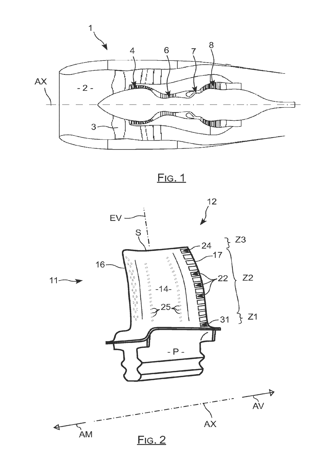
[0032]The vane according to the invention which appears in FIG. 2 by being referred to as 11 includes a root P carrying a blade 12 extending along a span direction EV which is radial with respect to its axis of rotation AX. The blade 12 extends from a base or platform through which it is connected to the root P up to an apex S corresponding to its free end, and it includes a suction face wall as well as a pressure face wall 14.

[0033]The suction face and pressure face 14 join each other on the one hand at the leading edge 16 of the blade which corresponds to its upstream region AM, and on the other hand at its tapered trailing edge 17 which corresponds to its downstream region AV. The upstream and downstream extend with respect to the circulation direction of the fluid surrounding the blade during operation.

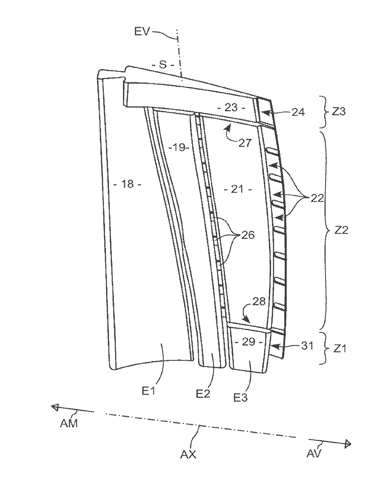
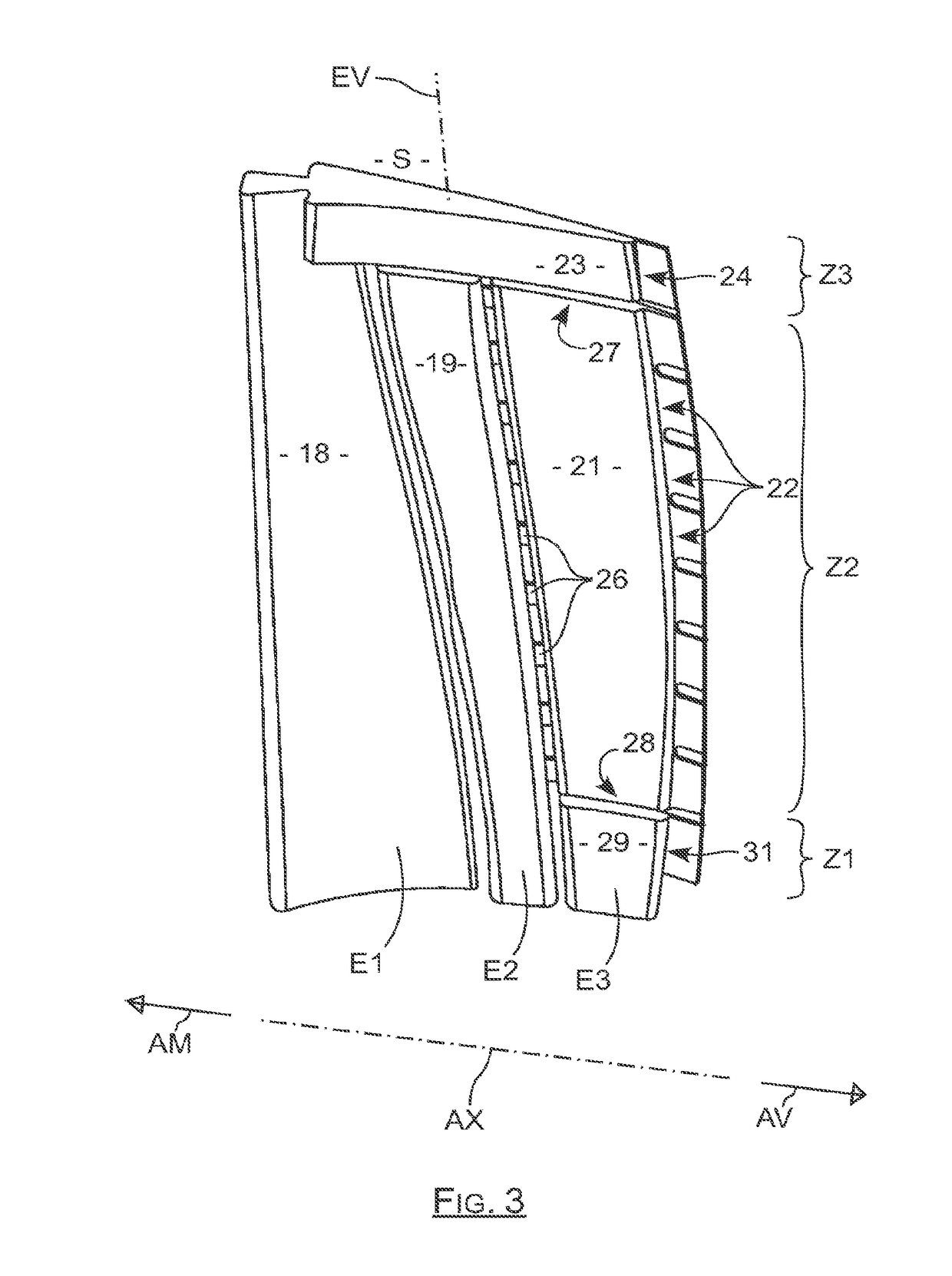
[0034]As visible in FIGS. 3 and 4, the inside of this vane includes a central duct 18 downstream of which a downstream duct 19 which comes along the central duct 18 to supply a do...


PUM


Abstract

A turbine blade including a root bearing an aerofoil extending in a direction of span and ending in a tip, this aerofoil including a leading edge and a trailing edge which are connected by a pressure face wall and a suction face wall, the trailing edge including on the pressure face side cooling slots. The trailing edge includes one or more first slots close to the root, which are supplied via a lower cavity; one or more last slots near the tip which are supplied via an upper cavity; intermediate slots situated between the first slots and the last slots supplied with air via a downstream line set; and wherein the lower cavities and upper cavities and the downstream line set are supplied distinctly at the level of the root.

Description

TECHNICAL FIELD[0001]The invention relates to a vane of an aircraft engine of the turbomachine type, such as for example a dual flow turbofan engine or a dual flow turboprop engine.STATE OF PRIOR ART[0002]In such an engine 1, outside air is taken into an inlet duct 2 to pass through a fan 3 including a series of rotating blades before being split into a central primary flow and a secondary flow surrounding the primary flow.[0003]The primary flow is then compressed by passing through a first and a second compression stage 4 and 6, before coming into a combustion chamber 7, after which it expands by passing through a set of turbines 8 before being rearwardly discharged, generating thrust. The secondary flow is in turn directly rearwardly propelled by the fan to generate a further thrust.[0004]The expansion in the turbines 8, which enables the compressor 4, 6 and the fan 3 to be driven, takes place at a high temperature because it immediately happens after combustion. This turbine 8 is...

Claims


Application Information

Patent Timeline
IPC IPC(8): F01D5/18B22C9/10
CPCF01D5/186B22C9/103F05D2260/202F05D2240/122F05D2230/21F01D5/187Y02T50/60
Inventor ENEAU, PATRICECONGRATEL, SEBASTIEN SERGE FRANCISDUJOL, CHARLOTTE MARIEPICOT, PHILIPPE
Owner SN DETUDE & DE CONSTR DE MOTEURS DAVIATION S N E C M A
Why Eureka
Eureka Blog
Learn More