
Systems and Methods for Electronic Measurement of Propeller Blade Angle

a technology of electronic measurement and propeller blade angle, which is applied in the direction of rotors, instruments, machines/engines, etc., can solve the problems of unsafe flight conditions, wear and contamination of turbine engines, and failure to meet the requirements of flight conditions,

Active Publication Date: 2018-10-25
GENERAL ELECTRIC CO
View PDF8 Cites 10 Cited by
  • Summary
  • Abstract
  • Description
  • Claims
  • Application Information

AI Technical Summary

Benefits of technology

The invention has several benefits that can be realized. The patent describes these benefits in a brief way, but more information can be found by practicing the invention.

Problems solved by technology

Conventional blade feedback systems often include numerous parts, components, and / or assemblies that are generally heavy and expensive, frustrating weight reduction and performance of turbine engines.
Moreover, conventional blade feedback systems are typically rigged external to the propeller hub and thus they are subject to wear and contamination from exposure to various elements (weather, dust, rocks, etc.).
The rigging features can also come out of adjustment during operation, leading to unsafe flight conditions and unreliable feedback of the propeller blade angles.

Method used


Image

  • Systems and Methods for Electronic Measurement of Propeller Blade Angle
  • Systems and Methods for Electronic Measurement of Propeller Blade Angle
  • Systems and Methods for Electronic Measurement of Propeller Blade Angle

Examples


Embodiment Construction

[0035]Reference now will be made in detail to embodiments of the invention, one or more examples of which are illustrated in the drawings. Each example is provided by way of explanation of the invention, not limitation of the invention. In fact, it will be apparent to those skilled in the art that various modifications and variations can be made in the present invention without departing from the scope or spirit of the invention. For instance, features illustrated or described as part of one embodiment can be used with another embodiment to yield a still further embodiment. Thus, it is intended that the present invention covers such modifications and variations as come within the scope of the appended claims and their equivalents.

[0036]As used herein, the terms “first”, “second”, and “third” may be used interchangeably to distinguish one component from another and are not intended to signify location or importance of the individual components.

[0037]The terms “upstream” and “downstre...


PUM


Abstract

Blade feedback systems and methods for determining a blade angle position and rotational speed of a plurality of propeller blades of a variable pitch propeller assembly are provided. Exemplary blade feedback system includes features for determining an axial position of a beta tube. Based at least in part on the axial position of the beta tube, the blade angle of the plurality of propeller blades can be determined. Exemplary blade feedback system can also include features for determining the rotational speed of the beta tube such that the rotational speed of the propeller blades can be determined.

Description

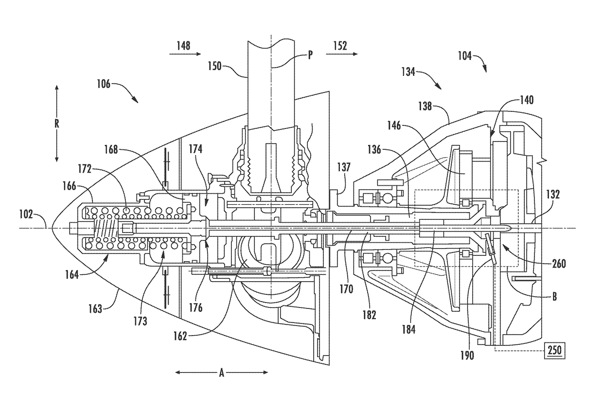
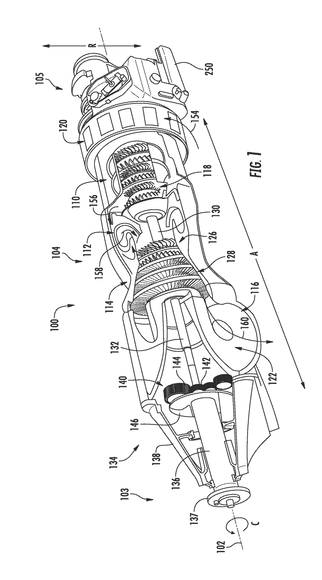
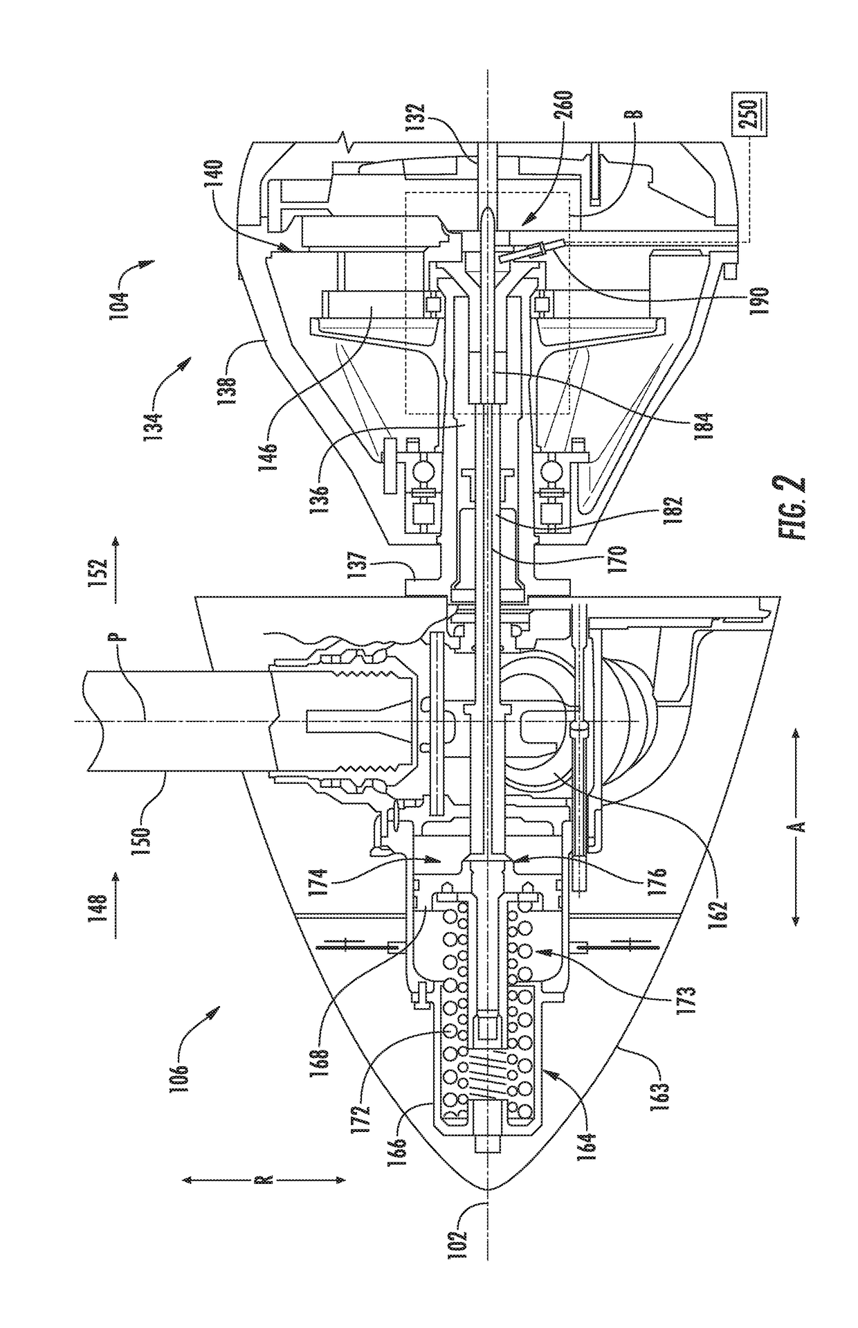
FIELD[0001]The present subject matter is generally related to variable pitch propeller assemblies.BACKGROUND[0002]Turbine engines, such as wind turbines and turboprop gas turbine engines, may include pitch adjustment mechanisms at a propeller assembly to adjust the pitch or blade angle of the propeller blades. Pitch adjustment of the propeller blades may increase turbine engine performance during various conditions (e.g., wind speed, altitude, or power output / input). Some propeller assemblies include a blade feedback system for determining the blade angle position of the propeller blades. By knowing the blade angle position of the propeller blades, turbine engine performance can be optimized.[0003]Conventional blade feedback systems often include numerous parts, components, and / or assemblies that are generally heavy and expensive, frustrating weight reduction and performance of turbine engines. Moreover, conventional blade feedback systems are typically rigged external to the propel...

Claims


Application Information

Patent Timeline
Patent Type & Authority Applications(United States)
IPC IPC(8): F01D21/00F01D5/02F01D5/12F01D7/00G01D5/22G01D5/24
CPCF01D21/003F01D5/02F01D5/12F05D2220/36G01D5/2291G01D5/24F05D2220/32F01D7/00F03D17/00F02C9/22F03D7/0204G01D5/241G01D5/145G01D5/20G01P3/481B64C11/06B64C11/301Y02E10/72
Inventor CHAPMAN, CHRISTOPHER MICHAEL
Owner GENERAL ELECTRIC CO
Learn More