High-pressure fuel pump

a fuel pump and high-pressure technology, applied in the direction of liquid fuel engines, positive displacement liquid engines, corrosion prevention fuel injection, etc., can solve the problems of undesired visual appearance, cylinder head corrosion, etc., to reduce noise emissions, reduce installation costs, and avoid negative appearance

Active Publication Date: 2018-10-25
ROBERT BOSCH GMBH
View PDF0 Cites 11 Cited by
  • Summary
  • Abstract
  • Description
  • Claims
  • Application Information

AI Technical Summary

Benefits of technology

[0004]Said object is achieved in that an electrical plug with a lateral line connector is mounted onto the electrically actuated suction valve, and in that the protective cap, in a first embodiment, is formed in two parts and has two protective cap parts. The object is likewise achieved in that an electrical plug with a lateral line connector is mounted onto the electrically actuated suction valve, and in that the protective cap, in a second embodiment, is of ring-shaped form and has a clearance slot which interrupts the ring-shaped protective cap. The protective cap formed in this way can, in both embodiments, be mounted on an assembled high-pressure fuel pump without the need for the electrical plug of the electrical connector line for the actuation of the electrically actuated valve having to be removed. In this way, the reliability of the installation of the high-pressure fuel pump is increased through the avoidance of a situation in which the electrical plug has to be dismounted for the purposes of mounting the protective cap and is possibly subsequently mounted again incorrectly. Here, the protective cap that can be mounted in this way furthermore performs further tasks. The pump cylinder head of the high-pressure fuel pump is produced from a metallic material, preferably as a cast part, and is mechanically blank on its surface pointing toward the surroundings. In particular, the pump cylinder head is not covered by a corrosion prevention means, for example in the form of a lacquer. The pump cylinder head can therefore corrode over the course of time without impairing the function of the high-pressure fuel pump, which constitutes an undesired visual appearance. Since the pump cylinder head is however covered with the protective cap formed according to the invention, this negative appearance is avoided. Furthermore, the protective cap constitutes a noise shield, which is effective in suppressing noise emissions originating from the high-pressure fuel pump. Finally, the protective cap constitutes a thermal guard for example for preventing the high-pressure fuel pump, that has warmed up during operation, from being touched. Since the electrical plug is manufactured from a non-metallic material, in particular from a plastics material, said electrical plug can perform the functions discussed above in addition to the protective cap, such that the protective cap designed according to the invention can have an aperture region in the region of the electrical plug without restricting functionality. In other words, said aperture region thus in particular forms a recess around the electrical plug.
[0005]The protective cap formed in two parts may be composed of two entirely independent protective cap parts, which are connected to one another during the mounting process. For this purpose, the two protective cap parts preferably each have a detent hook which engages into a corresponding detent groove of the second protective cap part. The two protective cap parts may however also be connected to one another at one side by means of a hinge, wherein, during the mounting process, the two protective cap parts are pivoted about the pump cylinder head and are connected to one another on the opposite side in relation to the hinge by means of the detent hook that engages into the detent groove. Here, the parting plane of the two protective cap parts preferably lies transversely with respect to the axis of the high-pressure fuel outlet. Furthermore, in the region of the high-pressure outlet, one protective cap part has a downwardly open recess, whereas the second protective cap part is formed without a recess. The protective cap thus formed from two protective cap parts can be mounted very easily.
[0008]In a further embodiment of the invention, it is preferable for both protective cap parts to have in each case one domed projection which extends in the direction of the electrical plug. When the protective cap has been mounted, said domed projection forms a ring which surrounds a sleeve nut by means of which the suction valve is fastened to the pump cylinder head. Here, the domed projection may be formed so as to directly adjoin the electrical plug, so as to realize a visually unitary appearance of said components. The protective cap with the protective cap parts and the domed projection are preferably manufactured from a plastics material, and can thus be easily produced in a corresponding injection mold. Here, the abovementioned hinge may easily be designed as a connecting lug of the two covering parts, in particular as a film hinge. Finally, by means of this embodiment, a possible ingress of water into the suction valve is reduced in that a partition with respect to the lower region of the sleeve nut can be realized by means of the protective cap.
[0009]The protective cap of ring-shaped form with the clearance slot which interrupts the ring-shaped protective cap is fitted over the electrical plug with the line connector, and the clearance slot is thus aligned relative to the lateral high-pressure fuel outlet such that the latter is arranged in the clearance slot when the protective cap has been mounted. The protective cap thus formed can be mounted easily in the case of an electrical plug with a lateral or upwardly directed line connector, wherein the lateral cable exit of the electrical plug may be pivoted through any desired angle with respect to the lateral high-pressure fuel outlet. In all possible embodiments, the protective cap is fitted with the clearance slot firstly over the line connector (with the onward-leading lines) of the electrical plug, and the protective cap is then pivoted such that the clearance slot is aligned in the direction of the lateral high-pressure fuel outlet. The protective cap is then pushed downward onto the pump cylinder head.

Problems solved by technology

The pump cylinder head can therefore corrode over the course of time without impairing the function of the high-pressure fuel pump, which constitutes an undesired visual appearance.

Method used


Image

  • High-pressure fuel pump
  • High-pressure fuel pump
  • High-pressure fuel pump

Examples


Embodiment Construction

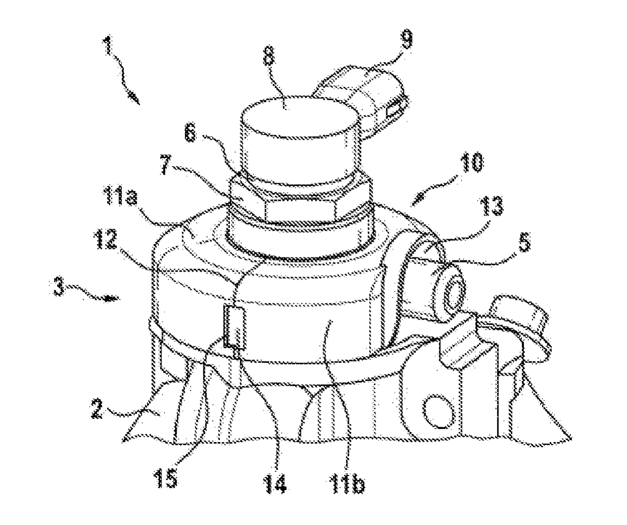
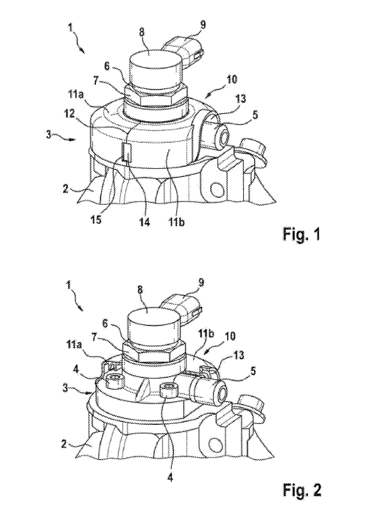
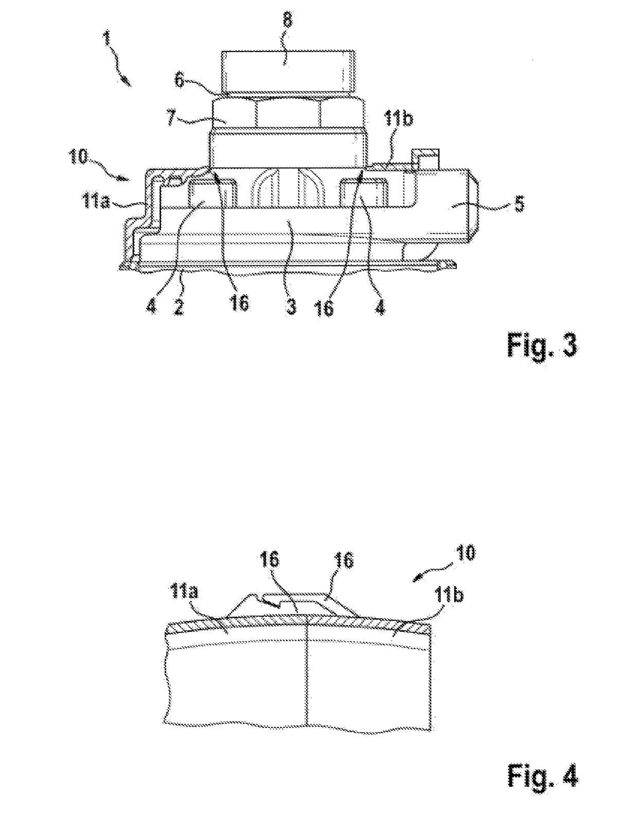
[0024]FIGS. 1 and 2 show the upper part of a high-pressure fuel pump 1 having a pump housing 2 on which a pump cylinder head 3 (see in particular FIG. 2) is mounted. By contrast to FIG. 1, FIG. 2 shows a protective cap 10 that has been sectioned in the plane of the high-pressure fuel outlet 5, in order to provide a better illustration of the pump cylinder head 3. The pump cylinder head 3 is fastened to the pump housing 2 by means of four screws 4, and has a lateral high-pressure fuel outlet 5. A high-pressure line is fastenable to the high-pressure fuel outlet 5, through which high-pressure line the fuel delivered by the high-pressure fuel pump 1 is conducted into a high-pressure accumulator. The high-pressure fuel pump 1 is preferably part of a common-rail injection system which is installed on an internal combustion engine. Here, the high-pressure fuel pump 1 is fed with fuel from a low-pressure system through a feed arranged in the pump housing 2 and in the pump cylinder head 3, ...


PUM


Abstract

The invention relates to a high-pressure fuel pump (1), in particular of a common rail injection system of an internal combustion engine, having a pump cylinder head (3), having an intake valve (6) arranged in the pump cylinder head (3) in the direction of a pump cylinder axis, and a high-pressure fuel outlet (5) arranged laterally on the pump cylinder head (3), wherein a protective cap (10, 10a) at least partly covering the high-pressure fuel pump (1) is provided. According to the invention, a high-pressure fuel pump (1) having a protective cap (10, 10a) is provided, in which the protective cap (10, 10a) can be mounted without difficulty on an assembled high-pressure fuel pump (1). This is achieved in that a plug (8) having a lateral lead connection (9) is placed on the electrically operated intake valve (6), and the protective cap (10) is formed in two pieces and has two protective cap parts (11a, 11b) that can be fitted to each other, or else in that a plug (8) having a lateral lead connection (9) is placed on the electrically operated intake valve (6), and the protective cap (10a) is formed annularly and has a free clearance slot (19) interrupting the ring.

Description

BACKGROUND OF THE INVENTION[0001]The invention relates to a high-pressure fuel pump, in particular of a common-rail injection system of an internal combustion engine, having a pump cylinder head, having a suction valve arranged in the direction of the pump cylinder axis in the pump cylinder head, and having a high-pressure fuel outlet arranged laterally on the pump cylinder head, wherein a protective cap is provided which at least partially covers the high-pressure fuel pump.[0002]A high-pressure fuel pump of said type is known from DE 10 2013 211 176 A1. Said high-pressure fuel pump of a common-rail injection system of an internal combustion engine has a pump cylinder head which is formed in one piece with a pump cylinder. In the pump cylinder head, in the direction of the pump cylinder axis, there is arranged a suction valve via which fuel can be introduced into a pump working chamber. Furthermore, a high-pressure fuel outlet with a check valve is arranged laterally on the pump cy...

Claims


Application Information

Patent Timeline
Patent Type & Authority Applications(United States)
IPC IPC(8): F02M59/48F02M59/46F04B53/22
CPCF02M59/48F02M59/466F04B53/22F02M2200/09F02M2200/9015F04B53/16F04B53/002F02M2200/853F02M53/00F02M59/366F02M59/44F02B77/11F02M2200/852F02M2200/05F04B1/00F02M59/102F04B1/0404
Inventor LAEPPLE, KARL-HEINZLUCARELLI, FRANCESCOLINDEN, DIETMAR VAN DER
Owner ROBERT BOSCH GMBH
Why Eureka
Try Eureka