Torsional vibration damper

a technology of torsional vibration and damper, which is applied in the direction of vibration suppression adjustment, mechanical equipment, couplings, etc., can solve the problems of affecting the reciprocating motion of the rolling body and the torsional vibration caused on the rotary member, so as to prevent the generation of collision noise and abrasion powder, reduce the damage, and reduce the damage

Active Publication Date: 2018-10-25
TOYOTA JIDOSHA KK
View PDF2 Cites 3 Cited by
  • Summary
  • Abstract
  • Description
  • Claims
  • Application Information

AI Technical Summary

Benefits of technology

[0020]According to the embodiment of the present disclosure, when the rolling mass is displaced in the axial direction toward the rotary member by vibrations or the like, the flange portion is isolated away from the rotary member by an axial thrust force established as a result of contact between the second corner and the first corner. That is, the rolling mass can be prevented from being contacted to the rotary member during rotation of the rotary member 18. According to the embodiment of the present disclosure, therefore, sliding resistance between the flange portion of the rolling mass and the rotary member can be eliminated. For this reason, the rolling mass is allowed to oscillate smoothly.
[0021]Further, since the rolling mass is allowed to oscillate smoothly, a designed vibration damping performance of the torsional vibration damper can be ensured while limiting damages on the rotary member and the rolling mass. In addition, it is possible to prevent generation of collision noise and abrasion powder.

Problems solved by technology

That is, torsional vibration is caused on the rotary member by such torque pulse.
However, when the flange portion is brought into contact to the rotating body by the axial force, the reciprocating motion of the rolling body may be hindered by sliding resistance acting between the flange portion and the rotating body.

Method used


Image

  • Torsional vibration damper
  • Torsional vibration damper
  • Torsional vibration damper

Examples


Embodiment Construction

)

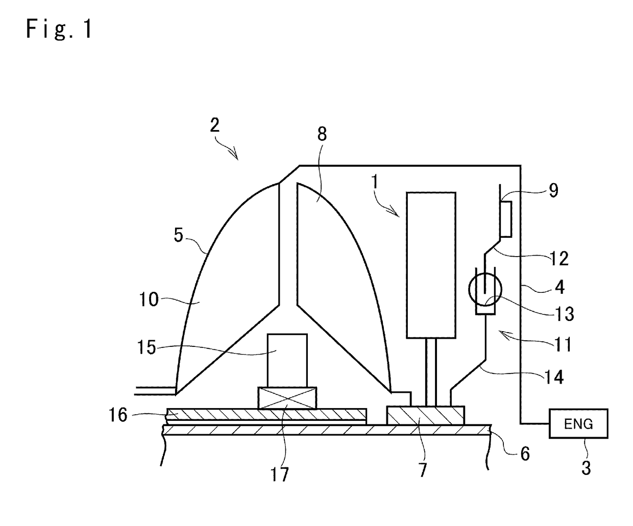
[0033]Preferred embodiments of the present application will now be explained with reference to the accompanying drawings. In FIG. 1, there is schematically shown a torque converter 2 having a torsional vibration damper 1 according to the embodiment. A front cover 4 extending from an engine 3 is connected to a pump shell 5 to form a housing of the torque converter 2, and an input shaft 6 of a not shown transmission penetrates through a center axis of the housing. A turbine hub 7 is fitted onto the input shaft 6 to be rotated integrally therewith while being connected to a turbine runner 8, a lockup clutch 9, and the torsional vibration damper 1.

[0034]As known in the conventional art, the turbine runner 8 is opposed to a pump impeller 10 to be rotated by a spiral oil flow created by the pump impeller 10. The lockup clutch 9 is hydraulically engaged with an inner face of the front cover 4 to enable torque transmission, and the torque transmission is interrupted by reducing hydraulic p...


PUM


Abstract

A torsional vibration damper in which vibration damping performance is ensured by preventing a contact between a rolling mass and a rotary member. A rolling mass includes a trunk penetrating through a bore. A first corner formed in an axial end of the trunk is rounded. A rotary member includes a second corner formed in the bore. an axial length of the first corner of the rolling mass is longer than an axial length of the second corner of the rotary member.

Description

[0001]The present disclosure claims the benefit of Japanese Patent Application No. 2017-085545 filed on Apr. 24, 2017 with the Japanese Patent Office, the disclosure of which is incorporated herein by reference in its entirety.BACKGROUNDField of the Disclosure[0002]The present disclosure relates to the art of a device for damping torsional vibrations utilizing reciprocating motion or oscillating motion of an inertial mass.Discussion of the Related Art[0003]A rotary member such as a drive shaft for transmitting torque generated by a prime mover is vibrated by pulsation of input torque or load torque by driving a member connected to the rotary member. That is, torsional vibration is caused on the rotary member by such torque pulse. Publication of Japanese patent No. 5928515 describes one example of an apparatus for reducing this kind of torsional vibration. In the torsional vibration reducing apparatus of Japanese patent No. 5928515, a rolling body is oscillated by torque pulse along ...

Claims


Application Information

Patent Timeline
Patent Type & Authority Applications(United States)
IPC IPC(8): F16F15/14F16F15/315
CPCF16F15/145F16F15/3153F16D3/12F16F2230/0082F16F15/12F16F15/14
Inventor HORITA, SHUHEIAMANO, HIROYUKISUZUKI, YUJIMIYAHARA, YU
Owner TOYOTA JIDOSHA KK
Why Eureka
Try Eureka