Autonomous Vehicle Corridor

a technology for autonomous vehicles and corridors, applied in vehicle position/course/altitude control, process and machine control, instruments, etc., can solve the problems of enormous localisation challenges of autonomous vehicles, and achieve the effect of improving safety and efficiency

Inactive Publication Date: 2018-10-25
KHAWAJA MUHAMMAD ZAIN +1
View PDF0 Cites 43 Cited by
  • Summary
  • Abstract
  • Description
  • Claims
  • Application Information

AI Technical Summary

Benefits of technology

[0022]In some embodiments, the possibility of offloading, any of the vision-perception tasks or component portions of other challenging tasks performed within an autonomous vehicle's software stack, from an autonomous vehicle's on-board systems to an infrastructure-deployed, perception-based, intelligent transport system (PB-ITS), one that incorporates perception-based intelligence into the context of an ITS, could create a system level perception redundancy contributing to higher levels of safety and efficiency for all connected-autonomous vehicles as well as for manually driven connected-vehicles. Leveraging perception-based intelligence, could help a connected-autonomous vehicle determine safe manoeuvres in advance of approaching an occluded part of the road or in advance of turning around a blind corner where visibility may not be available due to any limitations of the connected-autonomous vehicle's range-of-perception or field-of-view limitations and when there is no line-of-sight available even to a human driver, for example around a bend or a ‘blind-turn’. Leveraging perception-based intelligence also means, sharing perception outputs, and doing so, in a shared coordinate-frame, that is also shared, among various vision-perception sensors being either fixed or being upon any mobile platforms or vehicles.

Problems solved by technology

Without the map data being available, the autonomous vehicle faces tremendous challenges in achieving localisation within its operating context.
However, this perception redundancy, insofar as the maps are concerned, only relates to the permanent or non-transient type of road features along the autonomous vehicle's path.

Method used


Image

  • Autonomous Vehicle Corridor
  • Autonomous Vehicle Corridor
  • Autonomous Vehicle Corridor

Examples


Embodiment Construction

[0065]The following detailed description refers to the accompanying drawings. Embodiments of the present disclosure are described herein, however, it is to be construed that the disclosed embodiments are merely illustrative and explanatory and other embodiments can take various and alternative forms. The accompanying drawings are not to scale; some features could be exaggerated or minimized to show details of particular components. Therefore, specific structural and functional details disclosed herein are not to be interpreted as limiting, but merely as a representative basis for teaching one skilled in the art to variously employ the invention. As those of ordinary skill in the art will understand, various features illustrated and described with reference to any one of the drawings can be combined with features illustrated in one or more other drawings to produce embodiments that are not explicitly illustrated or described.

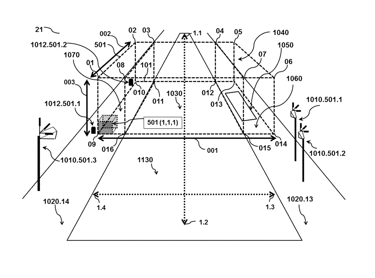
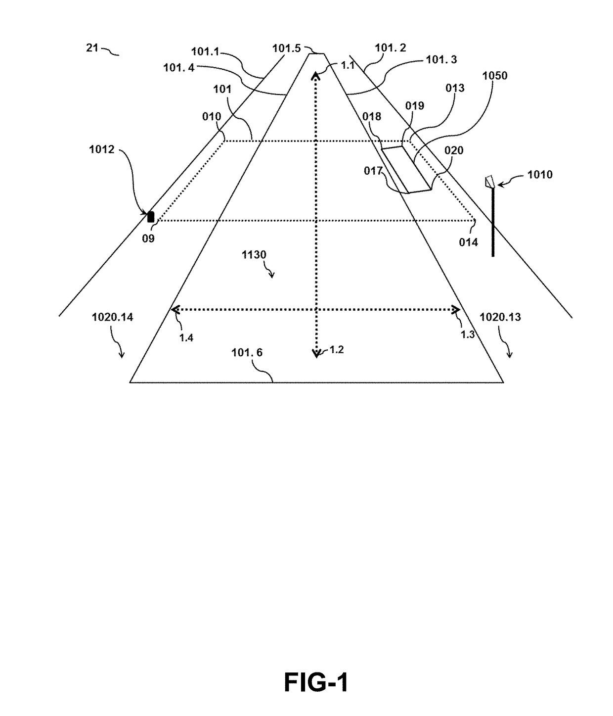
[0066]Reference is made to FIG. 1. A road segment is shown,...


PUM


Abstract

System and methods are provided for creating perception-based intelligence for augmenting the on-board capabilities of autonomous vehicles and for coordinating the traffic flow of connected-autonomous vehicles. Perception-based intelligence is created on the basis of leveraging the perception outputs of, one or more vision-perception sensors in various locations, while having a field-of-view, or a range-of-perception-sensing, of a pre-determined physical space. Perception-based intelligence is made shareable, in a shared coordinate-frame. Various methods are disclosed for encoding and representing the locations coordinates of perception outputs relating to transient, obstacles and any free-space, such that these encoded outputs, could be efficiently provisioned to various types of connected-autonomous vehicles, either directly or through an intelligent transport system. Systems and methods are disclosed for creating perception-based enablements, such as; look-ahead and non-line-of-sight perception, planned obstacle avoidance ahead of approach, autonomous-traffic flow coordination, autonomous-manoeuvre safety guidance, zone entry permissions and priorities for use-of-space or right-of-passage.

Description

BACKGROUNDTechnical Field[0001]The present disclosure relates generally to a system and methods, for creating perception-based intelligence for enabling safe autonomous navigation manoeuvres, as well as for coordinating road interaction among various types of connected-autonomous vehicles as well as manually driven connected-vehicles, within the context of any pre-determined physical space. Specifically, this disclosure teaches how such perception-based intelligence can be created, by utilising and leveraging perception outputs, of multiple vision-perception sensors, while these may be having a line-of-sight and field-of-view, or range-of-perception-sensing, of the pre-determined physical space. Additionally, this disclosure provides systems and methods, for variously encoding and representing the location coordinates of, transient, obstacles and free-space, being detected within the pre-determined physical space, in terms of a shareable coordinate-frame and variously creating diffe...

Claims


Application Information

Patent Timeline
Patent Type & Authority Applications(United States)
IPC IPC(8): G05D1/02G05D1/00
CPCG05D1/0276G05D1/0212G05D1/0022G05D1/0246G05D1/0274G05D1/0278G05D1/0282G05D2201/0213G08G1/162B60W30/00
Inventor KHAWAJA, MUHAMMAD ZAINILAHI, SABDEZAR
Owner KHAWAJA MUHAMMAD ZAIN
Why Eureka
Try Eureka