Self Recognition CNC Machining

a cellular workpiece and computer numerical control technology, applied in the field of machining, can solve the problems of increasing the complexity, duration, and cost of machining, increasing the likelihood of cutting drift in a correspondingly long machining path, and affecting the quality of machining, so as to increase the cost of manufacturing and prolong the processing time. , the effect of increasing the cost of manufacturing

Active Publication Date: 2018-10-25
THE NORDAM GRP
View PDF4 Cites 5 Cited by
  • Summary
  • Abstract
  • Description
  • Claims
  • Application Information

AI Technical Summary

Benefits of technology

[0024]And, the need to suitably clamp or stabilize the stock sheet and machine the multitude of individual cells ...

Problems solved by technology

Conventional processes may be used to machine such cell slots, but can experience various problems which undesirably increase the complexity, duration, and cost of machining
And, larger size workpieces increase the likelihood of drifting of the cut in a correspondingly long machining path due to small variations in workpiece placement atop the table.
Since the machine is controlled by an operator, the entire machining process can be labor intensive to ensure that mechanical alignment of the core sheet is maintained
The core cells may shift out of position into misalignment under the forces of ma...

Method used


Image

  • Self Recognition CNC Machining
  • Self Recognition CNC Machining
  • Self Recognition CNC Machining

Examples


Embodiment Construction

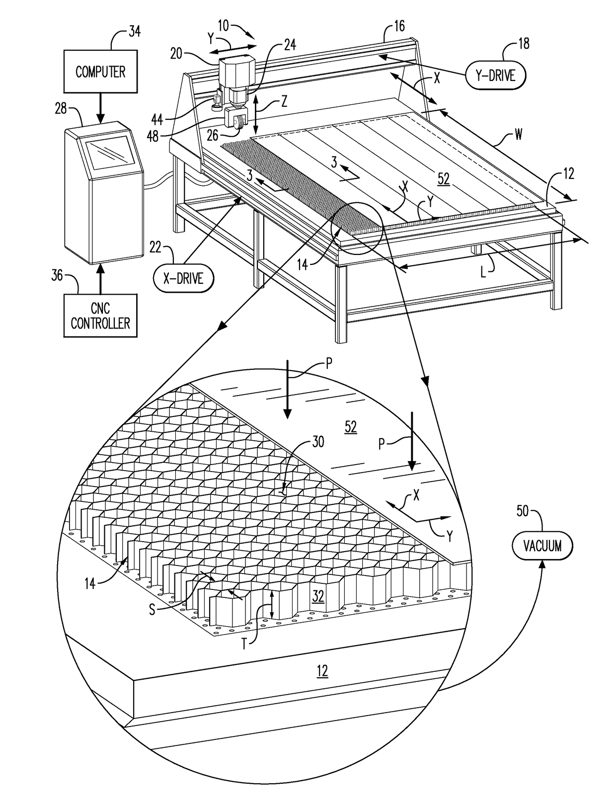
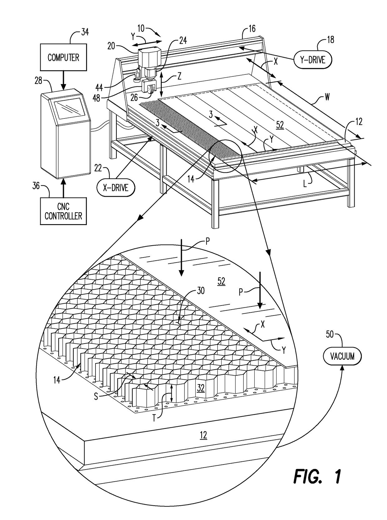
[0036]Illustrated schematically in FIG. 1 is a Computerized Numerical Controlled (CNC) cutting machine 10 in the exemplary form of a multi-axis CNC router which may be conventional in configuration and operation, except as modified hereinbelow in accordance with various features of the present invention.

[0037]The machine 10 includes a flat table 12 elevated from the floor by a stand or legs, upon which table 12 is supported or mounted a workpiece 14 in the exemplary form of a cellular core in flat rectangular sheet form, referred to hereinbelow as the core sheet 14, or simply core 14.

[0038]The machine 10 further includes an elevated bridge or gantry 16 extending longitudinally across the table 12 , and conventionally mounted to the table 12 by a lateral (X-axis) first drive system 18. A carriage 20 is conventionally mounted to the gantry 16 by a longitudinal (Y-axis) second drive system 22.

[0039]The carriage 20 is conventional and includes a vertical motor-driven spindle 24 to which...


PUM


Abstract

A method of machining a cellular core (14) includes mounting the core (14) atop a table (12) in a multi-axis Computerized Numerical Controlled (CNC) machine (10). The machine (10) is operated to self-scan the core (14) and self-recognize individual cells (30) arranged laterally in columns and longitudinally in rows. A machining path (E) is self-generated from the pre-recognized cells (30), and the core (14) is then machined along the self-generated machining path (E).

Description

BACKGROUND OF THE INVENTION[0001]The present invention relates generally to machining, and, more specifically, to Computerized Numerical Control (CNC) machining of a cellular workpiece.[0002]Honeycomb structural panels are commonly used in the aerospace industry in fabricating aircraft due to the high strength thereof and low weight. Such panels can be formed of various materials including synthetics and metals, and typically have a honeycomb core in sheet form bounded by opposite skins adhesively bonded thereto.[0003]In one exemplary application, an annular aircraft engine inlet is formed with small honeycomb core cells for effecting sound attenuation, with a structural outer skin, and an optional inner skin which would be perforated.[0004]The honeycomb core is initially obtained from various manufacturers in various configurations and materials, and is typically provided in large rectangular stock sheet form, such as 2 meters by 3 meters. The core itself may be relatively flexible...

Claims


Application Information

Patent Timeline
IPC IPC(8): G06N99/00G05B19/408G05B19/4093G01B11/00
CPCG06N99/007G05B19/4083G01B11/002G05B19/40937G05B19/40931G01B11/24G01B2210/52G05B19/4207G05B2219/50064G05B2219/37608G05B2219/45217G05B19/402
Inventor WHITE, DAVID ROSSDICKEY, JASON ADAM
Owner THE NORDAM GRP
Why Eureka
Try Eureka