Vehicle with fuel cell system mounted thereon

Active Publication Date: 2018-10-25
TOYOTA JIDOSHA KK
View PDF3 Cites 1 Cited by
  • Summary
  • Abstract
  • Description
  • Claims
  • Application Information

AI Technical Summary

Benefits of technology

The patent describes a fuel cell system that includes multiple tanks for storing fuel gas, valves for controlling the supply of fuel gas, and flow paths for delivering the fuel gas to the fuel cell. The system also has a merging flow path that combines all of the supply flow paths to deliver fuel gas to the fuel cell. The technical effect of this system is a more efficient and reliable supply of fuel gas to the fuel cell for efficient and reliable power generation.

Problems solved by technology

In a vehicle with the fuel cell system of JP 2006-120363 A mounted thereon, however, on condition that the merging flow path is fastened to the vehicle body, there is a problem that upon opening the opening / closing valve of a tank, vibrations due to discharge of the fuel gas compressed in the tank would be transferred via the merging flow path to the vehicle body so as to be perceived as noise for a vehicle passenger.
This noise, when perceived by the passenger, causes a fear that the passenger's mental image of the vehicle may be degraded.

Method used


Image

  • Vehicle with fuel cell system mounted thereon
  • Vehicle with fuel cell system mounted thereon
  • Vehicle with fuel cell system mounted thereon

Examples


first embodiment

A. First Embodiment

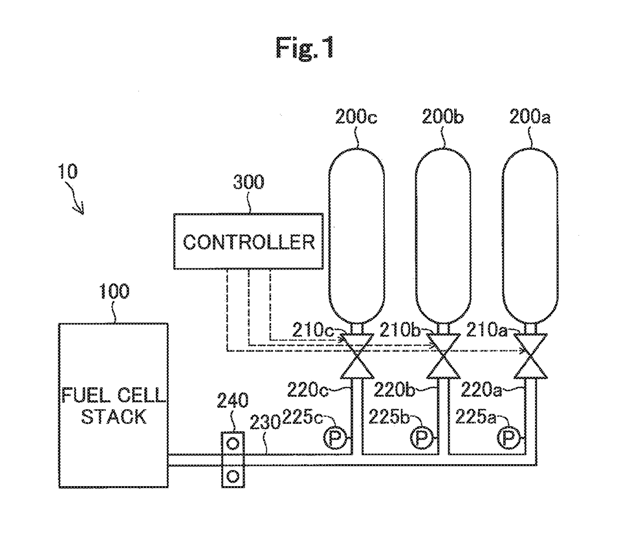
[0013]FIG. 1 is a block diagram showing a configuration of a fuel cell system 10 in a first embodiment of the present disclosure. The fuel cell system 10 is mounted on a motor-driven vehicle as a power source of the vehicle. The fuel cell system 10 includes a fuel cell stack 100, tanks 200a, 200b, 200c, supply flow paths 220a, 220b, 220c, a merging flow path 230, a fastening part 240, and a controller 300. Hereinbelow, the three tanks, when generically referred to, will be designated by using sign ‘200,’ and the three supply flow paths, when generically referred to, will be designated by using sign ‘220.’

[0014]The fuel cell stack 100 has a stack structure in which a plurality of unit cells are stacked in layers. Each unit cell is so structured that a membrane electrode assembly made by joining an anode and a cathode to both sides, respectively, of an electrolyte membrane having proton conductivity is held between separators. The fuel cell stack 100 is supplied wit...

modification 1

B1. Modification 1

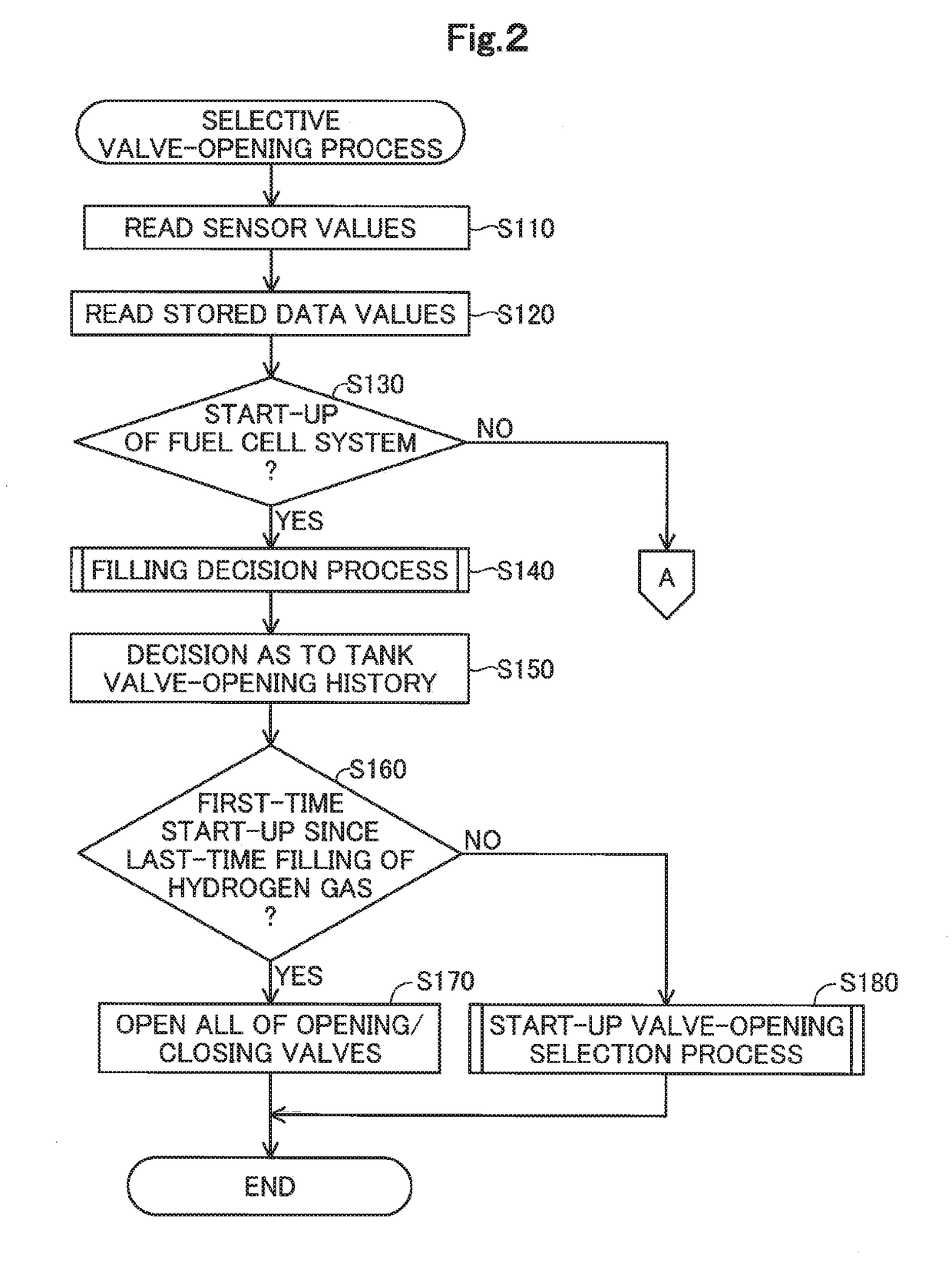
[0073]In the fuel cell system 10 of the first embodiment, whether or not the fuel cell system 10 is at a start-up is decided depending on whether or not the fuel cell stack 100 is enabled to supply a predetermined electric power. However, the present disclosure is not limited to this. For example, the fuel cell system 10 may also be so arranged that whether or not the fuel cell system 10 is at a start-up is decided depending on whether or not a predetermined time has elapsed after a turn-on of the ignition switch provided in the vehicle having the fuel cell system 10 mounted thereon.

modification 2

B2. Modification 2

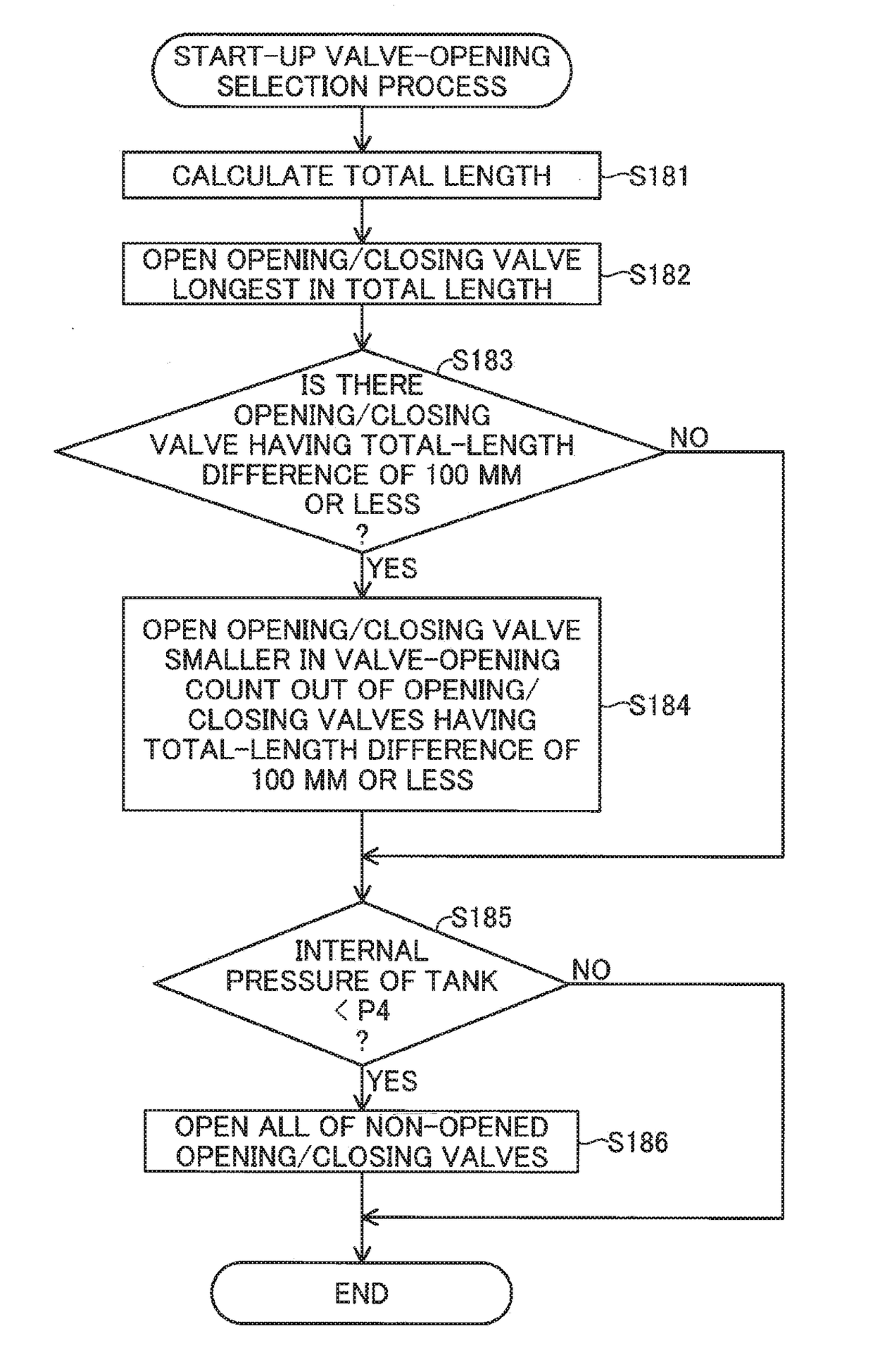
[0074]In the fuel cell system 10 of the first embodiment, all the opening / closing valves 210 are opened when a start-up of the fuel cell system 10 is a first-time start-up since the last-time filling of hydrogen gas into the tanks 200. However, the present disclosure is not limited to this. For example, the fuel cell system 10 may also be so arranged that not all of the opening / closing valves 210 are opened but only the opening / closing valve 210 having the longest total length is opened when the start-up of the fuel cell system 10 is a first-time start-up since the last-time filling of hydrogen gas into the tanks 200.


PUM


Abstract

Disclosed is a vehicle with a fuel cell system mounted thereon, the fuel cell system including: a fuel cell; a plurality of tanks for storing therein fuel gas to be used for power generation of the fuel cell, each tank having an opening / closing valve for switching over between execution and halt of supply of the fuel gas; a plurality of supply flow paths connected to the opening / closing valves in the plurality of tanks to feed the fuel gas supplied from the plurality of tanks, respectively; a merging flow path for merging together the plurality of supply flow paths to feed the fuel gas to the fuel cell; and a controller for controlling opening and closing of the opening / closing valves. The merging flow path is fastened to a vehicle body of the vehicle, and at a start-up of the fuel cell system, the controller exerts such control as to open an opening / closing valve that is longest in total length out of the opening / closing valves in the plurality of tanks, the total length being a total sum of lengths of the merging flow path and the relevant supply flow path located within a range from a fastening position, at which the merging flow path is fastened to the vehicle body, to each opening / closing valve. Thus, it becomes possible to suppress the possibility that noise caused by vibrations due to discharge of hydrogen gas may be recognized by a passenger of the vehicle.

Description

CROSS-REFERENCE TO RELATED APPLICATIONS[0001]The present application claims priority from Japanese patent application 2017-085956 filed on Apr. 25, 2017, the entirety of the content of which is hereby incorporated by reference into this application.BACKGROUNDField[0002]The present disclosure relates to a vehicle with a fuel cell system mounted thereon.Related Art[0003]Among fuel cell systems is one including: a fuel cell; a plurality of tanks which store fuel gas to be used for power generation by the fuel cell and which have opening / closing valves, respectively, for switching over between execution and halt of fuel gas supply; a plurality of supply flow paths connected to the opening / closing valves to feed the fuel gas; and a merging flow path for merging the plural supply flow paths together to feed the fuel gas to the fuel cell.[0004]In a vehicle with the fuel cell system of JP 2006-120363 A mounted thereon, however, on condition that the merging flow path is fastened to the vehi...

Claims


Application Information

Patent Timeline
IPC IPC(8): H01M8/04537H01M8/247
CPCH01M8/04559H01M8/247H01M2250/20H01M8/04201H01M8/04302H01M8/04089H01M8/04225Y02T90/40Y02E60/50Y02T10/70B60L58/30H01M8/04753B60L2240/12
Inventor YOSHIDA, NAOHIRO
Owner TOYOTA JIDOSHA KK
Why Eureka
Try Eureka