Photoelastic characterization of residual stresses and stress distributions in injection molded preforms and stretch blow-molded bottle

a technology of residual stress and photoelastic characterization, which is applied in the field of photoelastic characterization of residual stress, can solve the problems of insufficient understanding of residual stress molded into a preform, inability to make quantitative numerical predictions regarding and general inability to understand the effects of residual stress molded into the preform on the reheat stretch blow-blown molding dynamics, so as to reduce or minimize the expected stress distribution in the blow-blown bottl

Active Publication Date: 2018-11-01
THE COCA-COLA CO
View PDF0 Cites 6 Cited by
  • Summary
  • Abstract
  • Description
  • Claims
  • Application Information

AI Technical Summary

Benefits of technology

[0006]Among other things, the present disclosure provides for new and improved methods by which the residual stresses that are molded into a preform can be analyzed and methods by which data from such measurements can be employed to reduce or minimize the expected stress distribution in the blown bottle. In an aspect, photoelastic measurements on the preform and / or the bottle can be used to reveal the sequential complex evolution of the molded-in residual stress states in each molded part. Such data on the preform and / or the bottle subsequently can be used to adjust the injection molding and stretch blow-molding parameters to achieve reduced stress distributions in the final blown bottle.

Problems solved by technology

While numerical simulations can be employed to help understand the complicated interaction in this process sequence, the effects of residual stresses molded into the preform on the reheat stretch blow molding dynamics are generally not well understood.
As a result, the level of understanding of residual stresses molded into a preform is inadequate to make quantitative numerical predictions regarding the expected stress distribution in the blown bottle.

Method used


Image

  • Photoelastic characterization of residual stresses and stress distributions in injection molded preforms and stretch blow-molded bottle
  • Photoelastic characterization of residual stresses and stress distributions in injection molded preforms and stretch blow-molded bottle
  • Photoelastic characterization of residual stresses and stress distributions in injection molded preforms and stretch blow-molded bottle

Examples


example 1

on and Summary of Photoelastic Measurements on Selected Preforms and Stretch Blow-Molding Results for Bottles

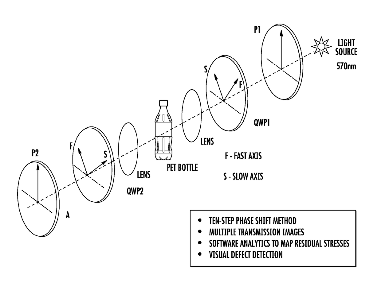
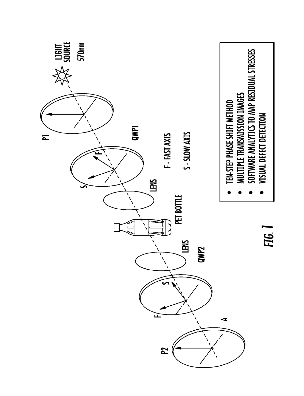
[0071]Several sets of PET and PEF bottles and preforms that had been manufactured under varying conditions were analyzed using a white-light digital polariscope. This information was used to first determine the stress-optic coefficients, then residual stresses were analyzed and classified in all samples. Several stress states were observed across the samples including uni-axial, bi-axial and hoop stress. Small material features were identified and cataloged in the bottles.

[0072]For the specific polymer used to fabricate the preform, a biaxially stretched sheet was made and used for calibration. Stress optic coefficient calibration was undertaken, where the stress optic coefficient for a birefringent material was calibrated by applying known stress field using a beam subjected to pure bending. The beam sample is free from stress and the small value of residual stress can be ig...

example 2

tal Validation and Further Examples for PEF Co-Polyester Resins

[0081]In Order to Further Examine this Concept for PEF Copolyester Resins, Four Unique 13 g preforms were designed to achieve areal stretch ratios (areal stretch ratio=axial stretch ratio×hoop stretch ratio) ranging from 11 to 29 across three straight wall bottle designs, ranging in size from 10 oz. to 16 oz. Table 3 provides a summary of selected relevant preform and bottle dimensions.

[0082]Preform Injection Molding Procedure.

[0083]The PEF resin was dried a minimum of 48 hours at 140° C. under vacuum. Each preform tooling was installed on an Arburg 420 injection molding machine with a valve-gated hot runner end cap and a 35 mm general purpose screw configuration. The injection molding conditions were optimized to produce acceptable preforms with minimum molded-in stresses and no visual defects at the minimum melt temperature.

[0084]Reheat Injection Molding Procedure.

[0085]All bottles were blown on a Sidel SB01 lab reheat...

example 3

Combinations of Inside Hoop Ratios and Axial Stretch Ratios for PEF Small Bottles

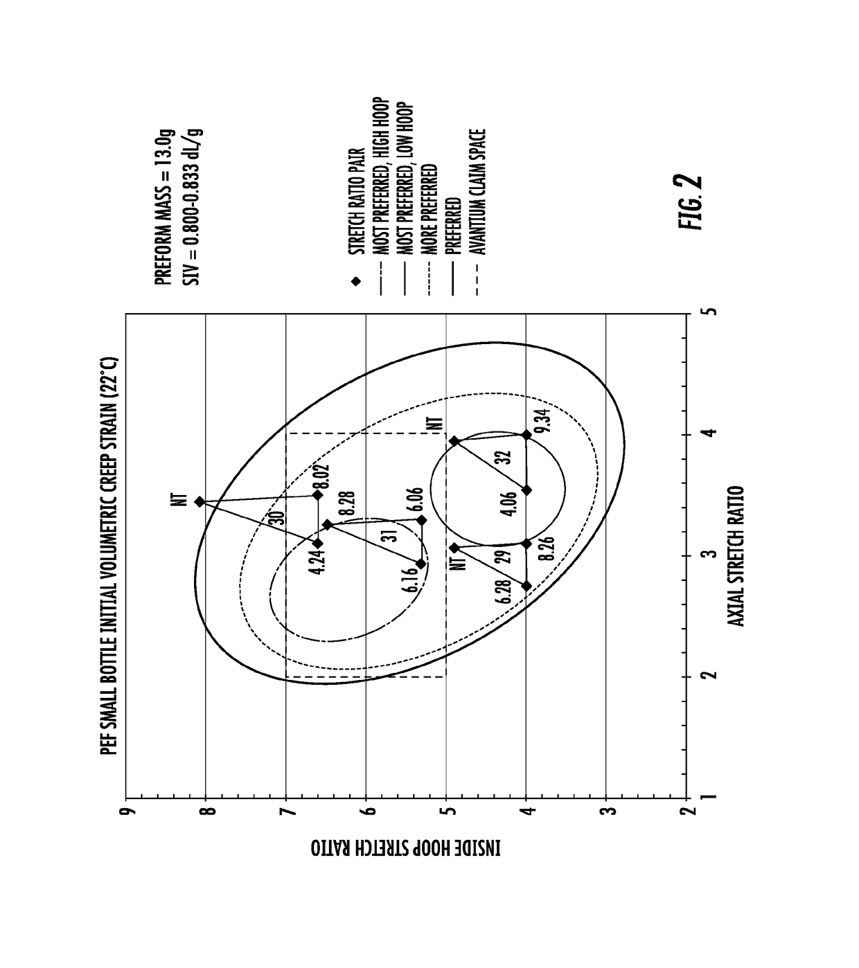
[0113]Referring to FIG. 2 and FIG. 3, a graphic illustration of PEF small bottle (13.0 g) initial volumetric creep strain (22° C.) tabulated on the plot itself (FIG. 2) and shelf life (weeks at 22° C., determined by FTIR) tabulated on the plot itself (FIG. 3) that correspond to successful combinations of inside hoop ratios and axial stretch ratios for PEF small bottles are presented. The innermost ellipses correspond to more preferred high hoop (red) and low hoop (orange) embodiments. The lowest volumetric creep and the highest FTIR shelf life at 22° C. was derived for PEF using the equibiaxial preform design with a 4.00×4.00=16.0 (axial stretch ratio×hoop stretch ratio=areal stretch ratio) and the 10 oz. bottle mold. All of the PEF bottles regardless of size (namely, 10, 12, or 16 oz.), reheat stretch blow molded from the same preform design, exhibited similar deformation modes distributed across the n...


PUM

PropertyMeasurementUnit
thicknessaaaaaaaaaa
thicknessaaaaaaaaaa
volumetric creep strainaaaaaaaaaa

Abstract

This disclosure provides new methods to characterize and relate residual stress and orientation imparted to the injection molded polymeric preform with orientation and residual stress in the resulting blow molded bottle. The method developed allows one to define and map the coupled thermal stress histories of both processes to define applicable preferred mutual processing windows for both preform and bottle molding processes. Stretch blow-molding parameters are developed using the disclosed method.

Description

CROSS REFERENCE TO RELATED APPLICATIONS[0001]This application claims the benefit of U.S. Provisional Application No. 62 / 247,834, which was filed on Oct. 29, 2015, which is incorporated herein by reference.TECHNICAL FIELD[0002]This disclosure relates to methods small and light-weight beverage packaging suitable for use with carbonated beverages and having good gas barrier properties.BACKGROUND[0003]Polyethylene terephthalate (“PET”) polymers and co-polymers are widely used to manufacture bottles for beverages such as water, juices, carbonated soft drinks (CSD), and the like, because they generally possess good mechanical and gas barrier properties. Such bottles are conventionally prepared using a stretch blow molding process. Stretch blow molding first involves injecting the PET polymer or co-polymer resin into a perform injection mold designed according to the desired final bottle shape and size and the polymer properties. The preform is subsequently reheated and stretch blow-molded...

Claims


Application Information

Patent Timeline
Patent Type & Authority Applications(United States)
IPC IPC(8): B29C49/78B29C49/12B29C45/76B29C49/06B29C49/64
CPCB29C49/78B29C49/12B29C45/76B29C49/06B29C49/6409B29K2995/0032B29L2031/7158B29B11/08B29C49/10B29K2995/0018B29K2995/0034B29K2067/003B29C2049/023B29C2049/7874B29C49/087B29C2049/7879
Inventor MOFFITT, RONALD D.SHI
Owner THE COCA-COLA CO
Why Eureka
Try Eureka