Smart additive manufacturing device

Active Publication Date: 2018-11-08
ADDITEC ADDITIVE TECH LLC
View PDF0 Cites 32 Cited by
  • Summary
  • Abstract
  • Description
  • Claims
  • Application Information

AI Technical Summary

Benefits of technology

[0008]In some embodiments, the deposition material enters through the center axis of the head with laser energy from multiple lasers angled to coincide with the material feed and work-piece at a precise focal point. Multiple fiber-coupled diode laser or fiber-coupled diode-pumped solid-state lasers (DPSSLs) provide high effective laser power. The design features the wire and powder feed material in separate channels through a coax arrangement with precision monit

Problems solved by technology

In this approach, either wire or powder feed material is used, but no capability

Method used


Image

  • Smart additive manufacturing device
  • Smart additive manufacturing device
  • Smart additive manufacturing device

Examples


Embodiment Construction

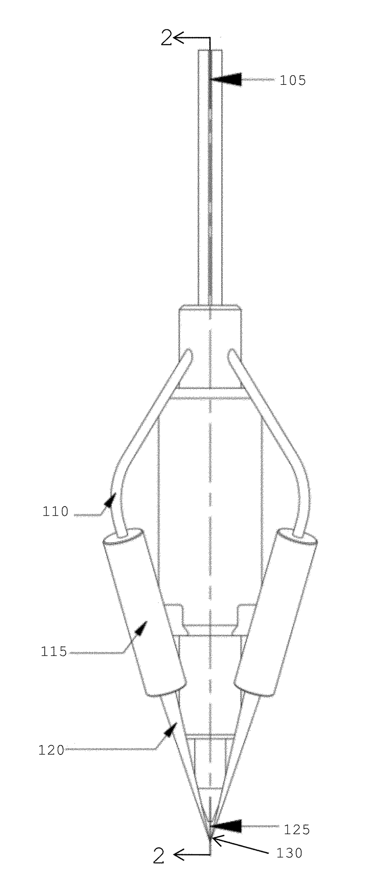
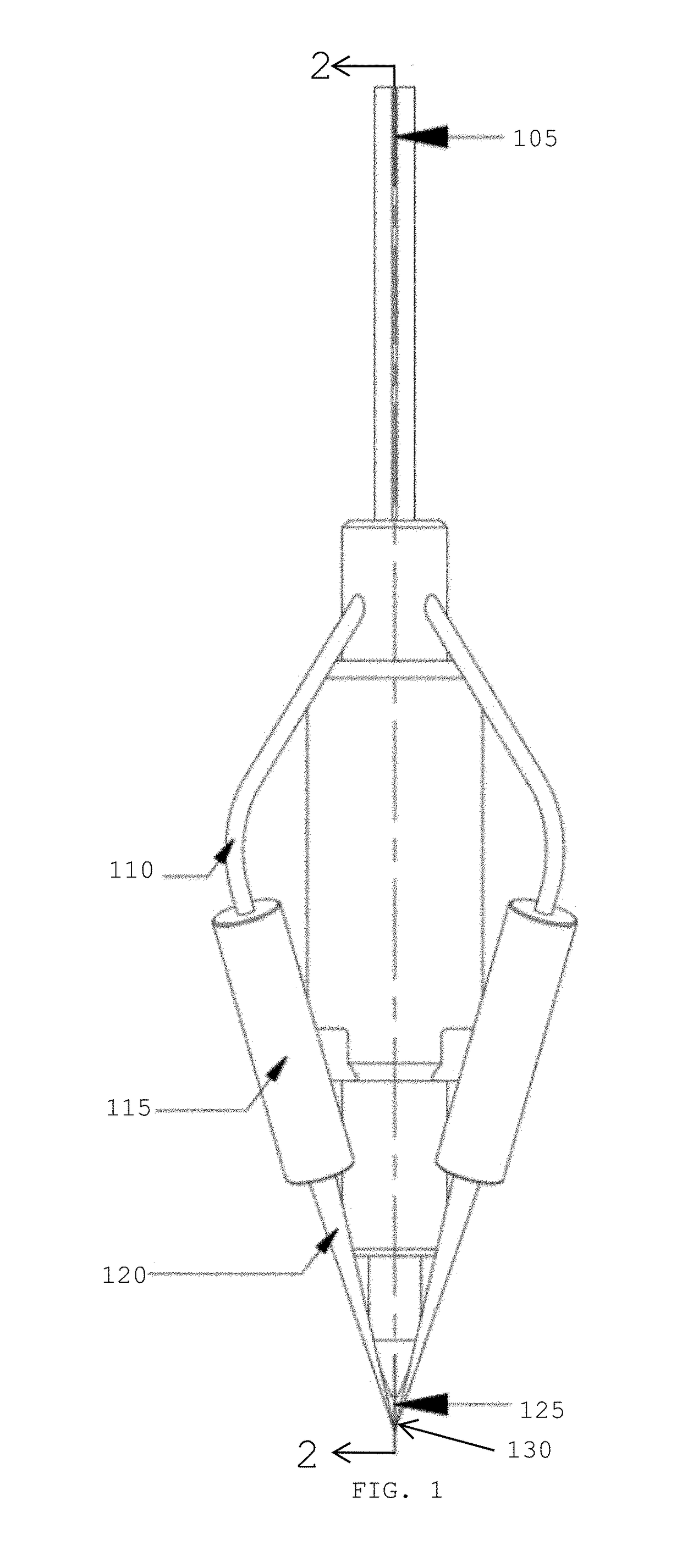
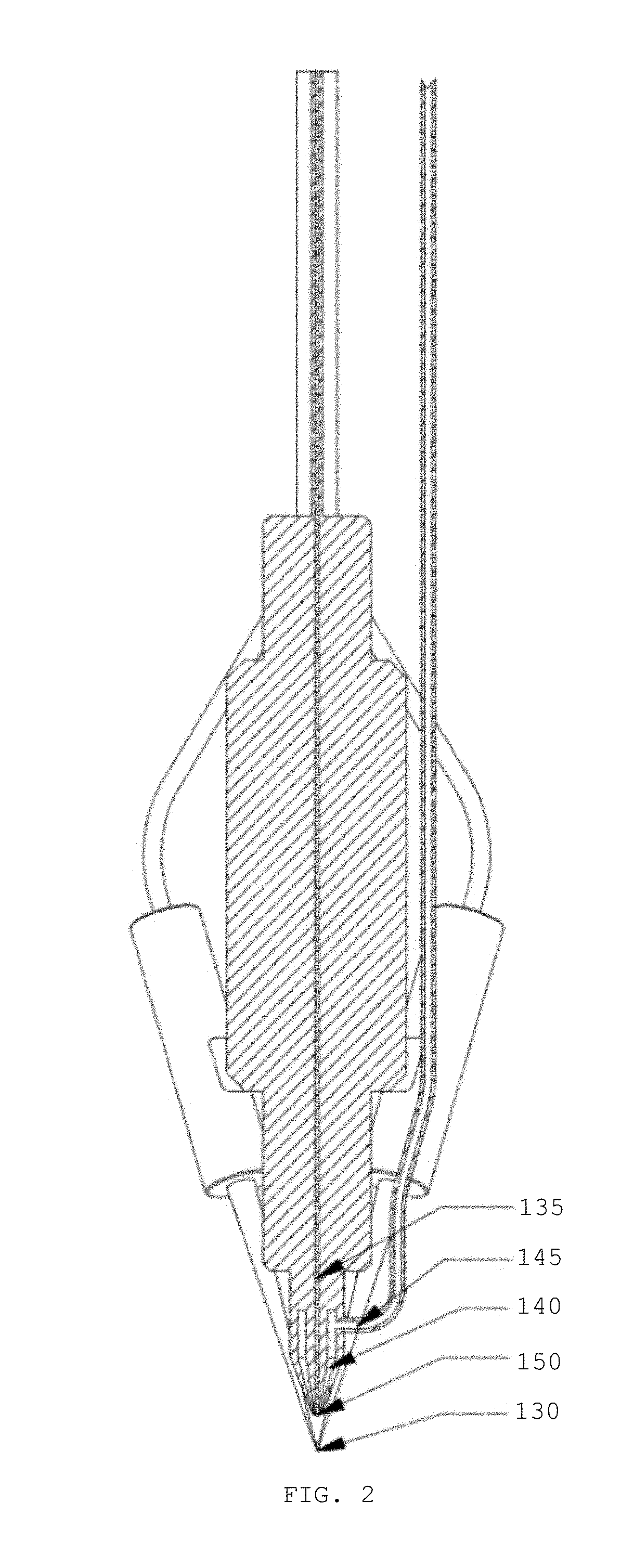
[0021]FIG. 1 shows a side view of an embodiment for a smart additive manufacturing device (deposition head) featuring its supply and laser fiber connections. Shown in FIG. 1 are a wire feed supply channel (105), a plurality of laser light fibers (110) emanating from a plurality of laser light sources, including but not exclusively, fiber-coupled diode lasers or fiber-coupled diode-pumped solid state lasers (DPSSLs), a plurality of off-axis laser light beams (120), a material feed (125), and a focal point for wire, powder and laser (130). Also shown are a plurality of off-axis laser light lens assemblies (115), which may be collimators in some embodiments, but are identified generically here as a plurality of off-axis laser light lens assemblies (115). Line 2-2 indicates that FIG. 2 is a cut-away view.

[0022]As shown in FIG. 1, a wire feed supply channel (105) supplies deposition feed stock such as wire though the deposition head. In some embodiments, the wire feed supply channel (105...


PUM

PropertyMeasurementUnit
Angleaaaaaaaaaa
Structureaaaaaaaaaa
Homogeneityaaaaaaaaaa

Abstract

Disclosed is a multiple-feature compact direct-metal deposition additive manufacturing (AM) print head. The head configures off-axis, solid-state diode or diode-pumped lasers into an array to perform precision controlled, direct metal deposition printing through a single print nozzle. Dual-mode printing capability using metal wire and powder feedstock sources in the same print nozzle is provided with in-line control, precision wire feed driver/controller, adjustable shield gas diffuser, and nozzles tailored to wire feedstock diameter.

Description

CROSS-REFERENCE TO RELATED APPLICATION[0001]This application claims the benefit of priority of U.S. Provisional Patent Application 62 / 606,135, filed May 2, 2017 and titled “Direct Deposition Device” and of U.S. Provisional Patent Application 62 / 508,535, filed May 19, 2017 and titled “TriAx Direct Deposition Device,” the disclosure of both of which are incorporated by reference.STATEMENT REGARDING FEDERALLY SPONSORED RESEARCH OR DEVELOPMENT[0002]Not ApplicableBACKGROUND OF THE INVENTIONField of Invention[0003]This invention relates generally to the field of manufacturing using additive manufacturing (AM) methods and, in particular, to a direct metal deposition (DMD) process utilizing a distributed laser light source to focus multiple laser beams on a build surface using laser-meltable metal feed material (wire or powder) to form a metal layered construct on a substrate under computer control.Description of Related Art[0004]Fabrication of three-dimensional metallic components using a ...

Claims


Application Information

Patent Timeline
IPC IPC(8): B22F3/115B33Y10/00B33Y30/00B22D23/00C23C4/123C23C4/18B23K26/08B23K26/06B23K26/12B23K26/14B23K26/342
CPCB22F3/115B33Y10/00B33Y30/00B22D23/003C23C4/123C23C4/185B23K26/0876B23K26/0604B23K26/0648B23K26/127B23K26/1464B23K26/342B23K26/0608B23K26/144
Inventor MATTHEWS, BRIANHOPPE, LUKAS
Owner ADDITEC ADDITIVE TECH LLC
Why Eureka
Try Eureka