Eureka AIR delivers breakthrough ideas for toughest innovation challenges, trusted by R&D personnel around the world.

Hydraulically actuated piston guided in a cylinder, and hydraulic working tool

Active Publication Date: 2018-11-08
GUSTAV KLAUKE GMBH
View PDF2 Cites 1 Cited by
  • Summary
  • Abstract
  • Description
  • Claims
  • Application Information

AI Technical Summary

Benefits of technology

The invention is designed to prevent excess wear and tear on hydraulic pistons during sudden eliminations of counter-pressure. When there is no counter-force, the piston can no longer or only very slightly “shoot forward” in the impact direction. The hydraulic medium decelerates the piston in the downstream hydraulic chamber, resulting in a force stored in the hydraulic medium. This cushioning effect against sudden piston movements can occur. The pressure difference caused by the limiting device can measure 20 to 70 bar, depending on the ratio between the active surfaces. The pressure in the impact space can rise up to 300 bar when there is no counter-force and then quickly drop down to almost zero when the piston comes to a stop.

Problems solved by technology

For example, when cutting comparatively thick wires, for example wires with a diameter of 5.6 or 8 mm, which further can consist of a steel material that is tends to undergo brittle fractures under pressure, there can be a sudden drop in the counter-force given such an exemplary brittle fracture of the wire to be cut, so that the piston experiences a very strong acceleration in a very short period of time.
As a result, very significant reaction forces can in turn arise in the device, since the piston as a rule immediately again experiences a correspondingly strong deceleration.
As a result, severe wear and tear can arise in the device after a few uses of this kind.

Method used


Image

  • Hydraulically actuated piston guided in a cylinder, and hydraulic working tool
  • Hydraulically actuated piston guided in a cylinder, and hydraulic working tool
  • Hydraulically actuated piston guided in a cylinder, and hydraulic working tool

Examples


Embodiment Construction

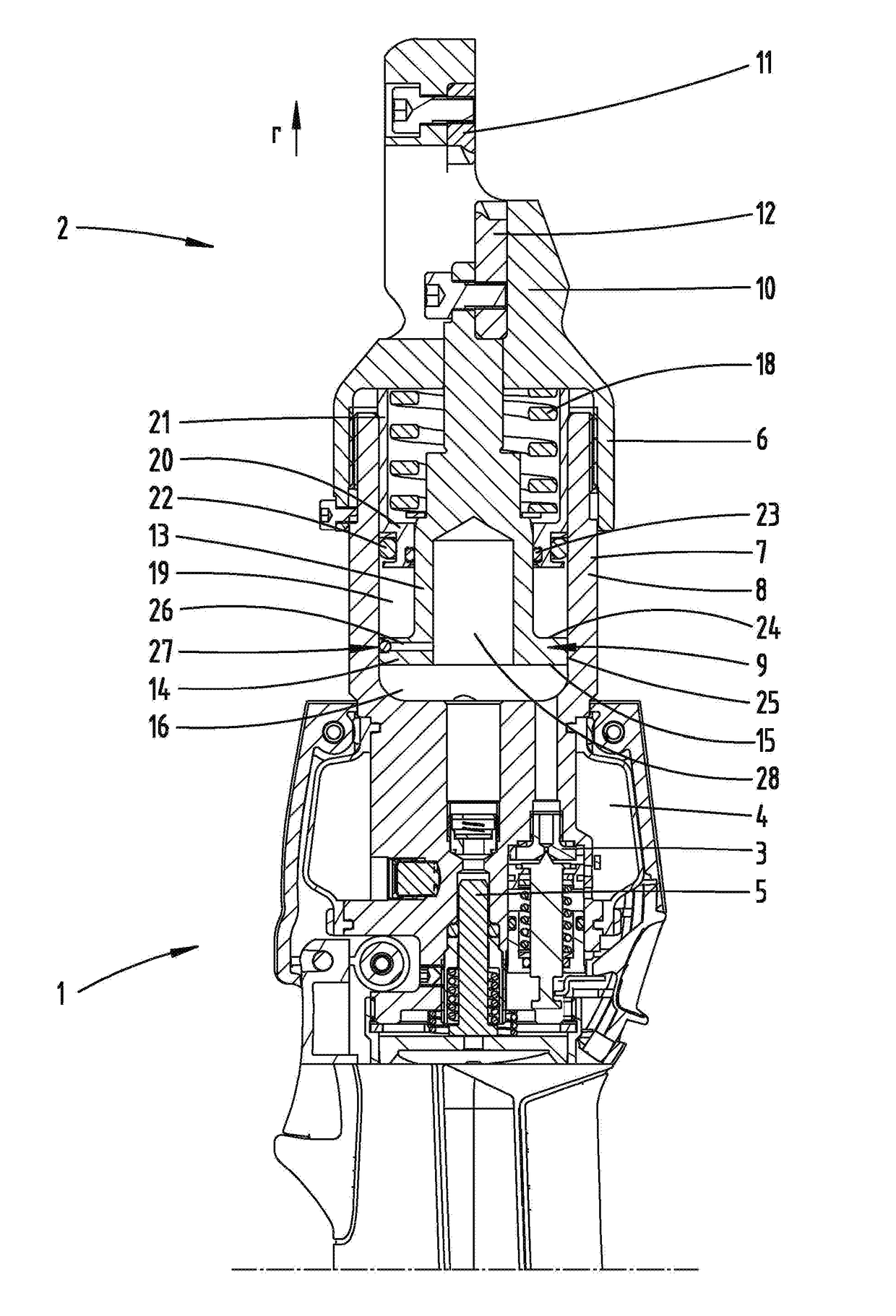
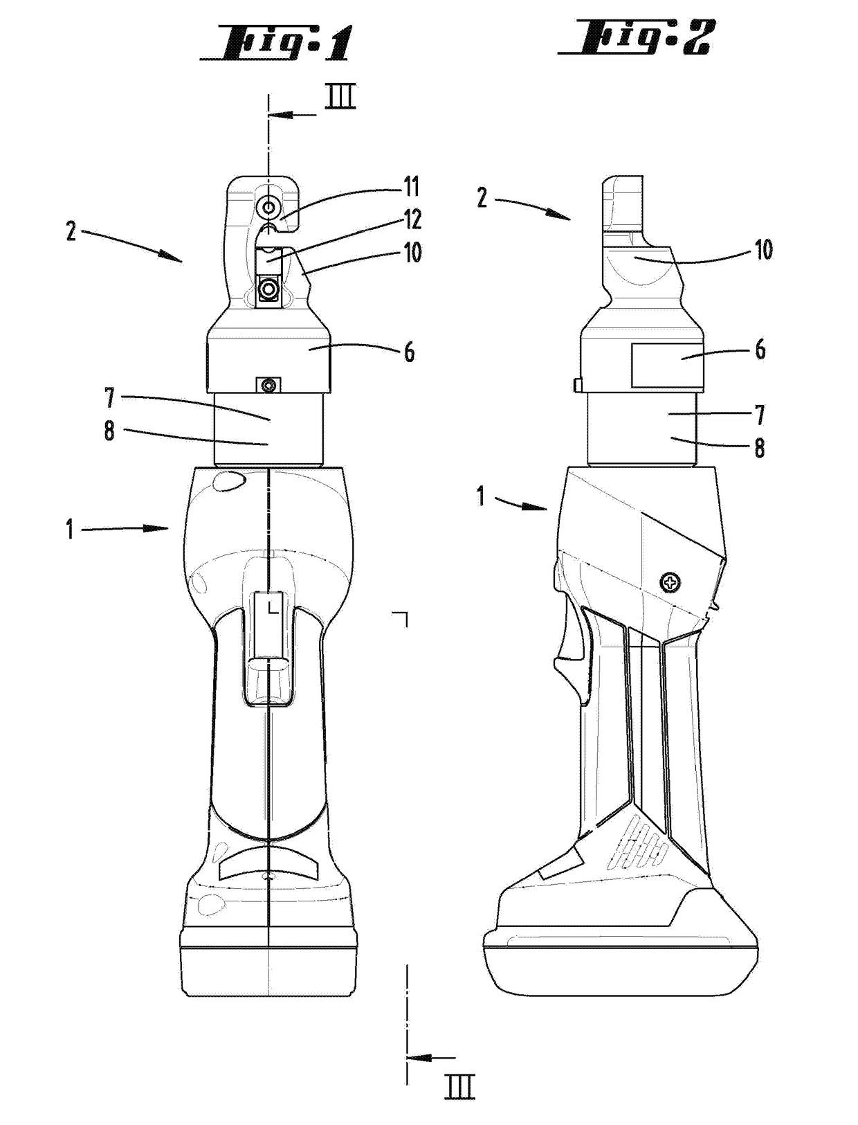
[0041]Depicted and described initially with reference to FIG. 1 is a hydraulic, in particular electrohydraulic working tool 1 suitable for one-handed operation for actuating a working head 2. As shown, the working head 2 can be designed as a head that can be interchangeably mounted on the working tool 1. A head non-detachably joined with the tool is likewise possible. The working head 2 is designed as a cutting head in the exemplary embodiment shown. However, working heads 2 in the form of punching or pressing heads can also be arranged on the working tool 1, for example.

[0042]The working head 2 can be hooked up to the working tool 1 for hydraulic supply purposes.

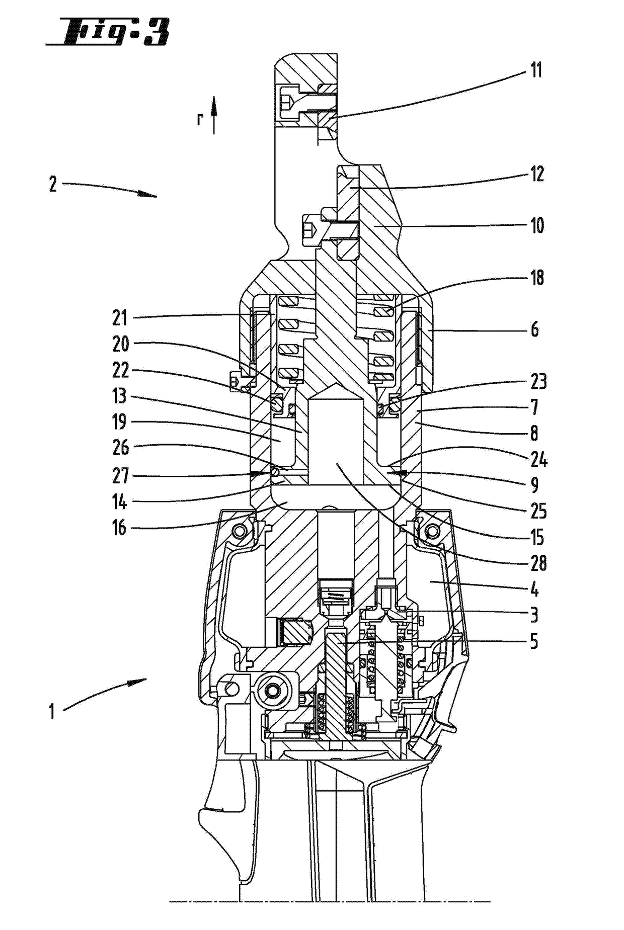
[0043]As also preferred, the hydraulic working tool 1 can be a base device of the kind also depicted and described in the WO 2003 / 084719 A2 (U.S. Pat. No. 7,412,868 B2) cited at the outset. With reference to the illustration on FIG. 3, the upper area of the working tool 1 reveals the link with the subject matter described i...


PUM

PropertyMeasurementUnit
Pressureaaaaaaaaaa
Volumeaaaaaaaaaa

Abstract

The invention relates to a hydraulically actuated piston (9) guided in a cylinder (8), and to a hydraulic working tool (1) having a working head (2), wherein the piston (9) has an impact surface (15) which borders an impact space (16) on the piston side provided between the piston (9) and the cylinder (8), and wherein hydraulic fluid (17) can act on the impact surface (15) by increasing the impact space (16) in order to move the piston (9) in an impact direction (r), and the piston (9) forms a limiting device (25) for a through-flow of the hydraulic fluid (17). According to the invention, in order to design a hydraulic piston guided in a cylinder or a hydraulic working tool in such a way that no undue signs of wear occur even during working processes with the sudden disappearance of the counter pressure, a hydraulic chamber (19) filled with the hydraulic fluid (17) is formed in the impact direction (r) after the limiting device (25), wherein a volume of the hydraulic chamber (19) is reduced according to the increase in the impact space (16), by means of the displacement of hydraulic fluid (17) out of the hydraulic chamber (19) and into the impact space (16) via the limiting device (25).

Description

AREA OF TECHNOLOGY[0001]The invention initially relates to a hydraulically actuated piston guided in a cylinder, wherein the piston has an impact surface that borders an impact space on the piston side provided between the piston and cylinder, wherein hydraulic fluid can further act on the impact surface by enlarging the impact space in order to move the piston in an impact direction, and the piston interacts with an inner surface of the cylinder to form a limiting device for the hydraulic fluid to flow through.[0002]The invention also relates to a hydraulic working tool with a working head and a hydraulically actuated piston guided in a cylinder, wherein the piston has an impact surface that borders an impact space on the piston side provided between the piston and cylinder, wherein hydraulic fluid can further act on the impact surface by enlarging the impact space in order to move the piston in an impact direction, and the piston interacts with an inner surface of the cylinder to ...

Claims


Application Information

Patent Timeline
IPC IPC(8): B25F5/00F15B15/14F15B15/20F15B15/22
CPCF15B15/204B26F1/34F15B15/225F15B15/1447B23D29/002F15B15/226B25F5/005B25B27/026B25B27/10F15B15/22F15B2211/7052F15B2211/755
Inventor FRENKEN, EGBERTLEHR, ANDREAS
Owner GUSTAV KLAUKE GMBH
Why Eureka
Eureka Blog
Learn More