Refrigeration cycle device and heat cycle system

a technology of refrigerating cycle and heat cycle system, which is applied in the direction of mechanical equipment, refrigeration components, light and heating equipment, etc., can solve problems such as deterioration of use components, and achieve the effect of safe operation

Inactive Publication Date: 2018-11-08
ASAHI GLASS CO LTD
View PDF0 Cites 16 Cited by
  • Summary
  • Abstract
  • Description
  • Claims
  • Application Information

AI Technical Summary

Benefits of technology

[0015]In the present invention, it is possible to avoid generation of sludge within a refrigeration cycle so that safe operation can be performed in spite of the use of a working fluid containing an HFO.

Problems solved by technology

When the hydrofluoroolefin is decomposed by the effect of water or oxygen, hydrofluoric acid is generated in a cooling cycle or a refrigeration cycle, causing deterioration of use components.

Method used


Image

  • Refrigeration cycle device and heat cycle system
  • Refrigeration cycle device and heat cycle system
  • Refrigeration cycle device and heat cycle system

Examples


Embodiment Construction

[0021]Embodiment for carrying out the present invention are described below with reference to the drawings.

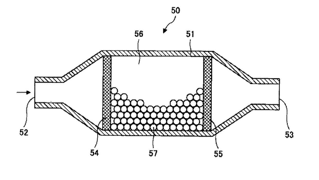
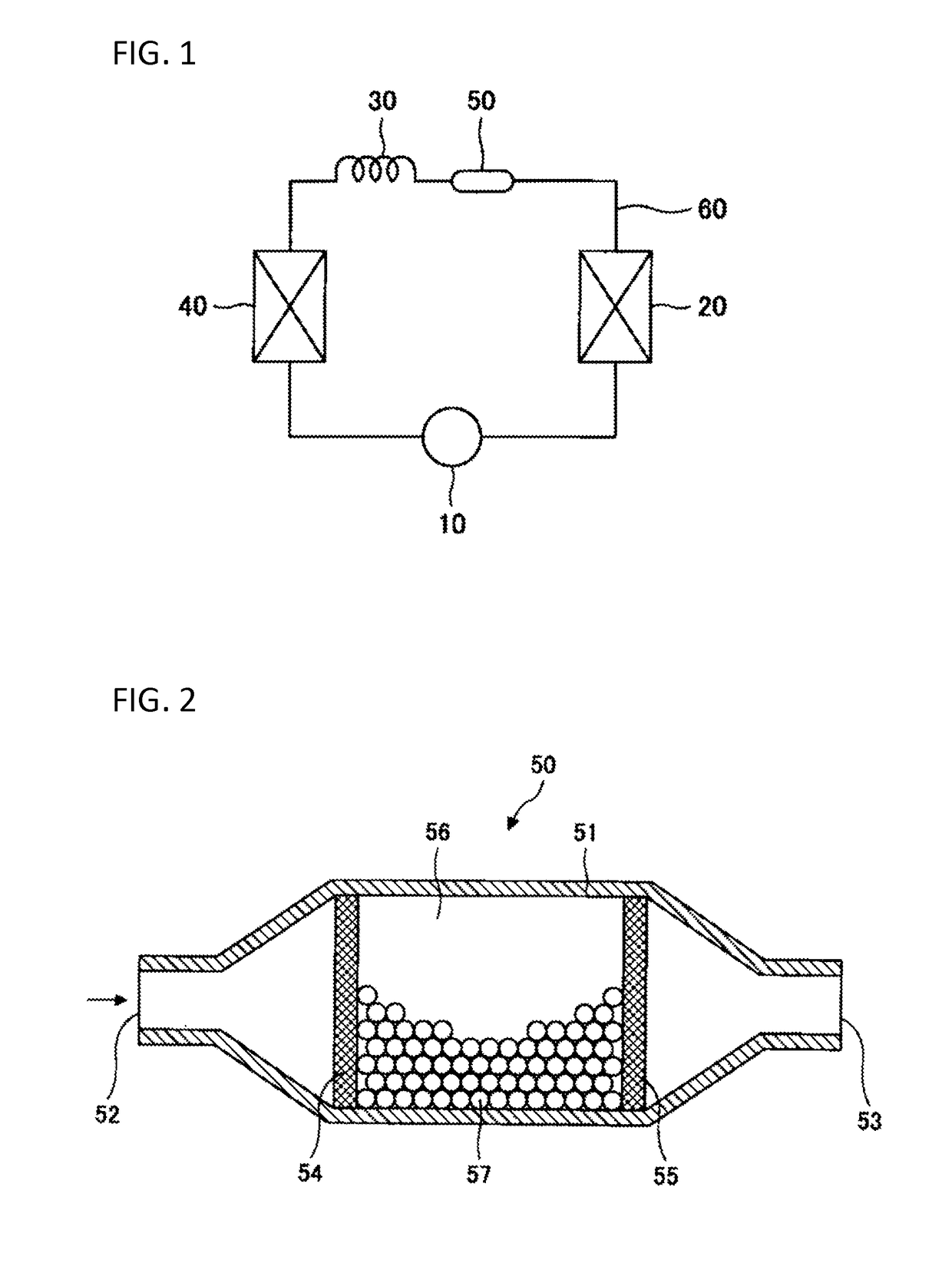
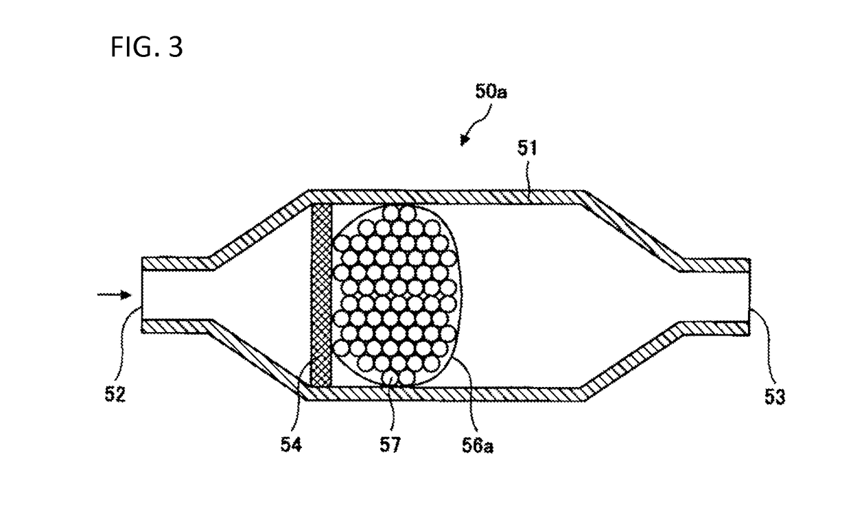
[0022]FIG. 1 is an overall configuration diagram illustrating an example of a refrigeration cycle apparatus in the embodiment of the present invention. As illustrated in FIG. 1, the refrigeration cycle apparatus in the embodiment includes a compressor 10, a condenser 20, a pressure reducing mechanism 30, an evaporator 40, a deoxidizing portion 50, and a pipeline 60. The compressor 10, the condenser 20, the pressure reducing mechanism 30, the evaporator 40 and the deoxidizing portion 50 are connected in an annular shape by the pipeline 60 so as to form a refrigeration cycle as a whole. In addition, in the refrigeration cycle apparatus in the embodiment, a working fluid containing an HFO is used as a working fluid. The details of the working fluid are described later. If water or oxygen is included within the refrigeration cycle, the HFO may be easily decomposed to generate sludg...


PUM


Abstract

A refrigeration cycle apparatus includes a compressor, a condenser, a pressure reducing mechanism and an evaporator and use a working fluid containing a hydrofluoroolefin (HFO). The compressor, condenser, pressure reducing mechanism and evaporator are connected with a pipeline to form a refrigeration cycle. A deoxidizing portion where the working fluid is brought into contact with a desiccant or a deoxidizer is provided at any place within the refrigeration cycle.

Description

TECHNICAL FIELD[0001]The present invention relates to a refrigeration cycle apparatus and a heat cycle system.BACKGROUND ART[0002]The following cooling cycle apparatus has been known in the background art: in the cooling cycle apparatus, a cooling compressor in which a refrigerator oil has been enclosed, a first heat exchanger, a refrigerant flow rate control portion such as a capillary tube and an expansion valve, a second heat exchanger placed in a space portion to be refrigerated or air-conditioned, and an accumulator are connected with a pipeline so as to constitute a refrigeration cycle; a single working fluid of a hydrofluoroolefin (HFO) or a mixed working fluid including a hydrofluoroolefin as its basic component is enclosed in the refrigerant cycle; and an adsorber which has been filled with an adsorbent for adsorbing substances having hydrofluoric acid as their main ingredient is provided in the cooling cycle (for example, see Patent Document 1).[0003]Similarly, the followi...

Claims


Application Information

Patent Timeline
Patent Type & Authority Applications(United States)
IPC IPC(8): F25B43/00F25B1/00F25B9/00F25B49/02F25B41/06
CPCF25B43/00F25B1/00F25B9/008F25B49/027F25B41/062F25B2600/021F25B2313/02741F25B9/002F25B47/003F25B2400/121
Inventor HAYAMIZU, HIROKIFUKUSHIMA, MASATOTAKAGI, HIROKAZU
Owner ASAHI GLASS CO LTD
Why Eureka
Try Eureka