Vehicle brake system

Active Publication Date: 2018-11-15
TOYOTA JIDOSHA KK
View PDF3 Cites 6 Cited by
  • Summary
  • Abstract
  • Description
  • Claims
  • Application Information

AI Technical Summary

Benefits of technology

[0006]In the vehicle brake system according to the present disclosure, when any one of the two systems is in failure, the braking force based on the driver's brake operation and the braking force based on the pressure of the working fluid from the controlled-pressure supply device are not generated at the same time. Thus, the operation feeling of the brake operation member is not deteriorated due to an influence of the pressure of the working fluid pressurized by the controlled-pressure supply device, so that the present vehicle brake system has high utility.
[0007]There will be exemplified and explained various forms of an invention that is considered claimable. (The invention will be hereinafter referred to as “claimable invention” where appropriate). Each of the forms is numbered like the appended claims and depends from the other form or forms, where appropriate. This is for easier understanding of the claimable invention, and it is to be understood that combinations of constituent elements that constitute the invention are not limited to those described in the following forms. That is, it is to be understood that the claimable invention s

Problems solved by technology

In this case, if the braking force is generated in the failed system by the working fluid pressurized by the master cylinder while the braking force is generated in the non-failed system by the working fluid supplied from the controlled-pressure supply device, there may be a risk that the pressure of the working fluid pressurized by the controlled-pr

Method used


Image

  • Vehicle brake system
  • Vehicle brake system
  • Vehicle brake system

Examples


Example

[0054]Referring to the drawings, there will be explained below in detail one embodiment of the claimable invention. It is to be understood that the claimable invention is not limited to the details of the following embodiment but may be embodied based on the forms described in Forms of the Invention and may be changed and modified based on the knowledge of those skilled in the art.

[A] Outline of Vehicle Drive System and Vehicle Brake System

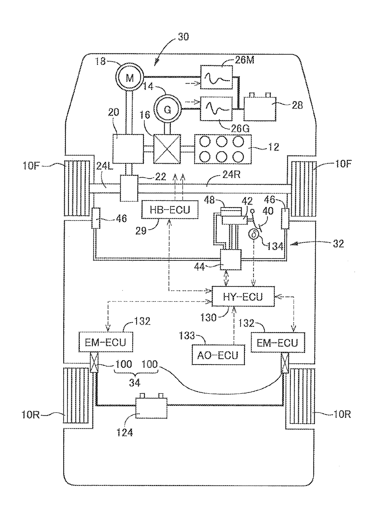
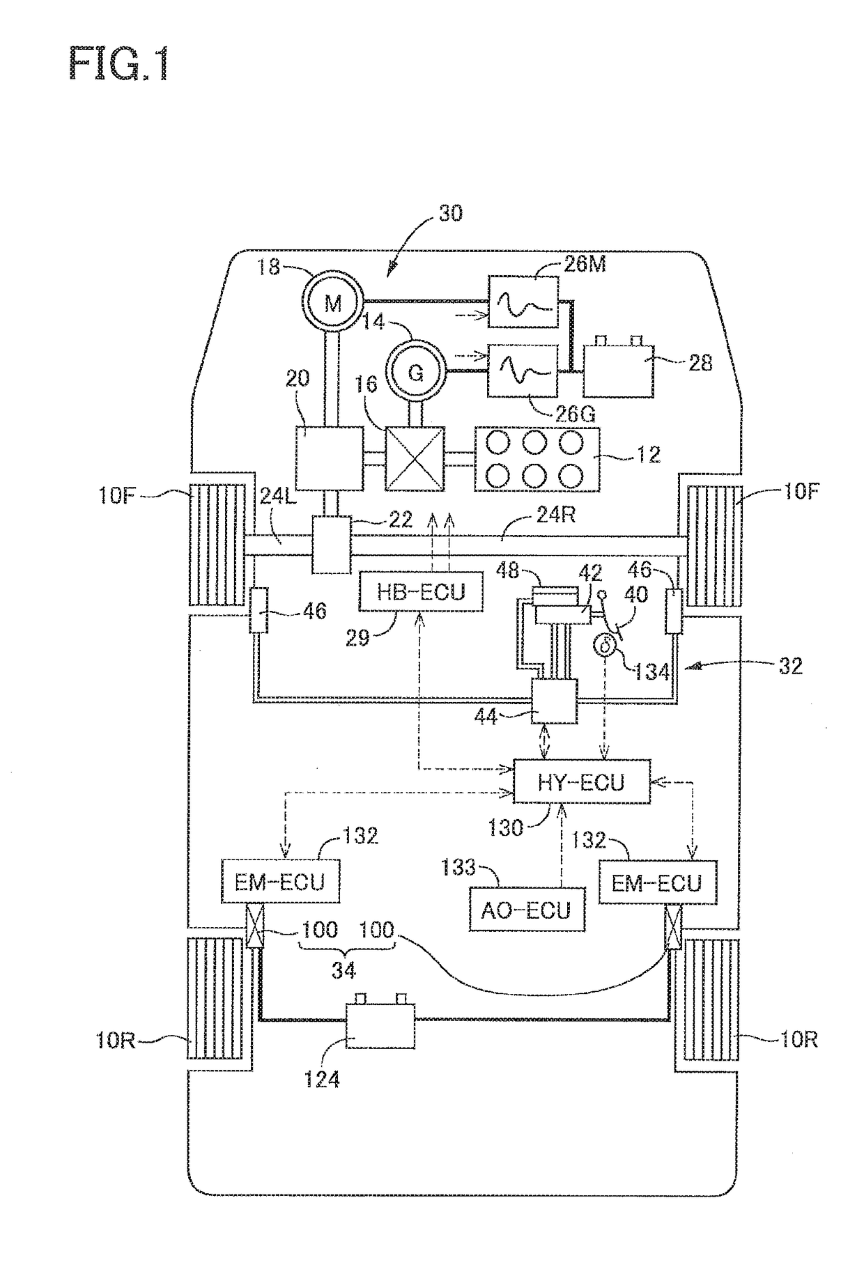
[0055]As schematically shown in FIG. 1, a vehicle on which a brake system according to one embodiment is installed is a hybrid vehicle having two front wheels 10F and two rear wheels 10R. The two front wheels 10F are drive wheels. A vehicle drive system is first explained. The vehicle drive system installed on the vehicle includes an engine 12 as a drive source, a generator 14 that functions mainly as an electric generator, a power-distribution mechanism 16 to which the engine 12 and the generator 14 are coupled, and an electric motor 18 as anothe...


PUM


Abstract

A vehicle brake system including a hydraulic brake device having two systems and configured to generate a braking force, wherein, in a failure condition of one of the two systems, one of the following two operation modes of the hydraulic brake device is selectively established: (a) a two-wheel mode in which master shut-off valves shut respective master fluid passages and a braking force that depends on a pressure of a working fluid supplied from a master cylinder is generated for each of right and left wheels; and (b) a one-wheel mode in which one of the master shut-off valves corresponding to the other of the two systems shuts off the corresponding master fluid passage and a braking force that depends on the working fluid supplied by a controlled-pressure supply device is generated for only one of the right and left wheels that corresponds to the other of the two systems.

Description

CROSS REFERENCE TO RELATED APPLICATION[0001]The present application claims priority from Japanese Patent Application No. 2017-095025, which was filed on May 11, 2017, the disclosure of which is herein incorporated by reference in its entirety.BACKGROUNDTechnical Field[0002]The following disclosure relates to a brake system for a vehicle installed on the vehicle.Description of Related Art[0003]A hydraulic brake device as described in Patent Literature 1 (Japanese Patent Application Publication No. 2011-51494) is known as one example of a hydraulic brake device configured to generate a braking force that depends on a pressure of the working fluid. Specifically, the known hydraulic brake device includes two systems for generating the braking forces for mutually different wheels. In a normal condition, the working fluid is supplied to the wheel brakes of both of the two systems not from a master cylinder but from a controlled-pressure supply device which has a high-pressure source and w...

Claims


Application Information

Patent Timeline
IPC IPC(8): B60T17/18B60T7/04B60T13/14B60T13/68B60T13/74
CPCB60T17/18B60T7/042B60T13/142B60T13/686B60T13/741B60T2220/04B60T2270/403B60T2270/402B60T8/4827B60T8/4081B60T8/94B60T8/4059
Inventor YAMAMOTO, NAOKI
Owner TOYOTA JIDOSHA KK
Why Eureka
Try Eureka