
Battery module

a battery module and battery technology, applied in the field of battery modules, can solve the problems of poor connection reliability module disassembly, and failure of the battery module function, and achieve the effects of simple and convenient connection, improved connection strength of the battery module, and reduced possibility of connection failure of the battery modul

Active Publication Date: 2018-11-15
CONTEMPORARY AMPEREX TECH CO
View PDF0 Cites 3 Cited by
  • Summary
  • Abstract
  • Description
  • Claims
  • Application Information

AI Technical Summary

Benefits of technology

The present patent provides a battery module that has a simple and accurate assembly process and ensures connection reliability between the end plates and side plates. This is achieved by designing the battery module with two end plates and two side plates connected by inserting portions on the side plates into groove portions on the end plates. This design improves the connection strength of the battery module and reduces the possibility of connection failure. The assembly process is simple and convenient, and ensures the connection reliability between the plates.

Problems solved by technology

The strength of the battery module is related to the safety performance, if the strength on the fixation is not enough, it will result in that the structure of the battery module is disassembled and the function of the battery module fails, even short circuit and fire occurs, which will cause personal safety.
However, because the bolt is easy to loose, connection reliability of the battery module using the bolt fixation is poor during the continuous vibration; anti-impact strength of the battery module using the bandage fixation is lower, the material of the bandage is lower in ability of resisting corrosion and aging, the connection reliability of the battery module is poor; the battery module using the end plate-side plate welding has high cost and the rate of scrapping, low assembling efficiency, and easily generate cracks inside the welded location, with the vibration of the battery module, the cracks will expand and finally result in failure of the connection between the end plates and the side plates.

Method used


Image

  • Battery module
  • Battery module
  • Battery module

Examples


Embodiment Construction

[0048]Hereinafter a battery module according to the present disclosure will be described in detail in combination with the figures.

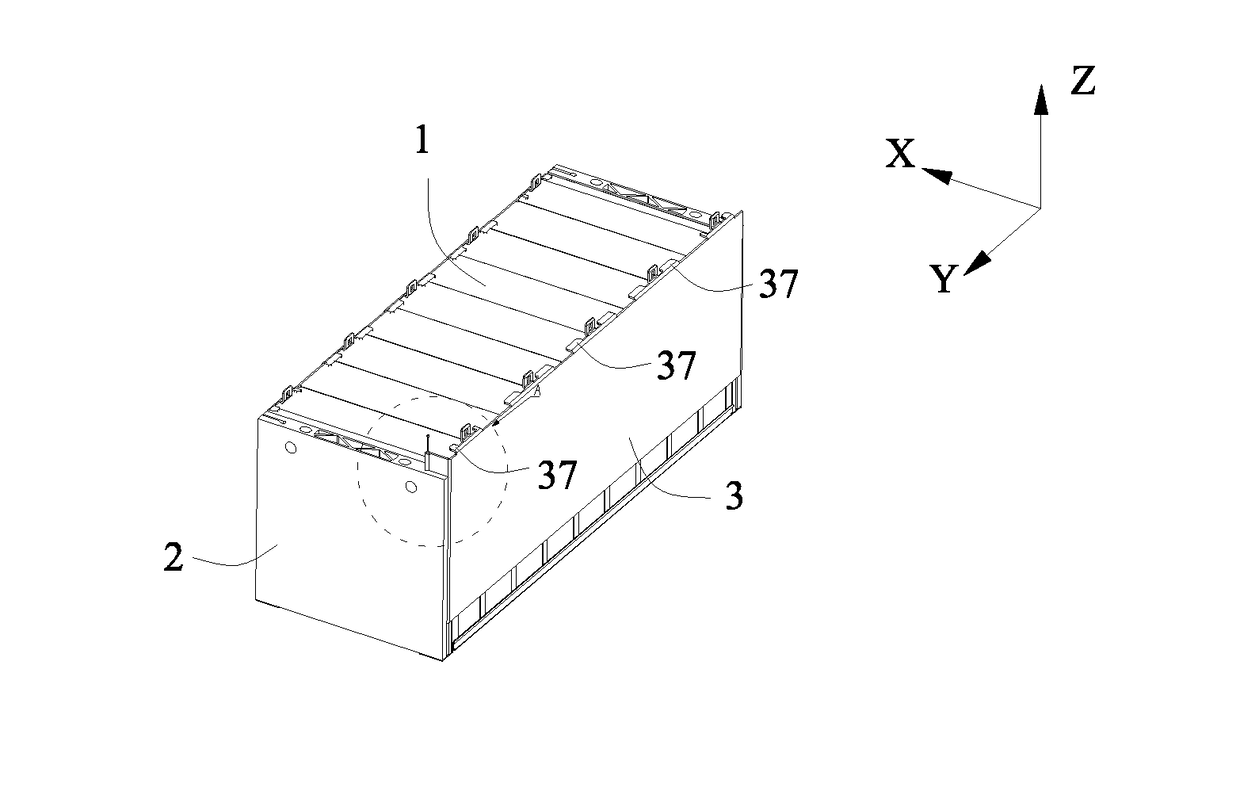
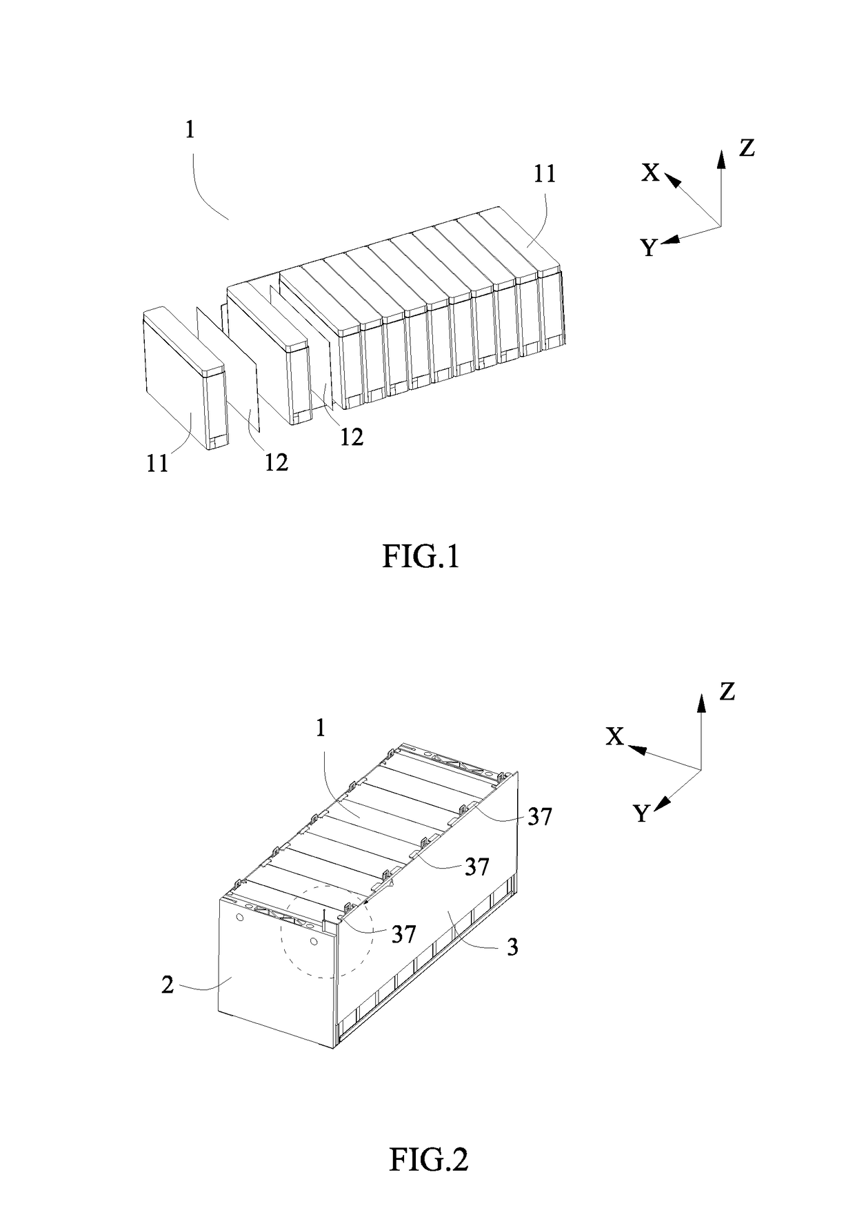
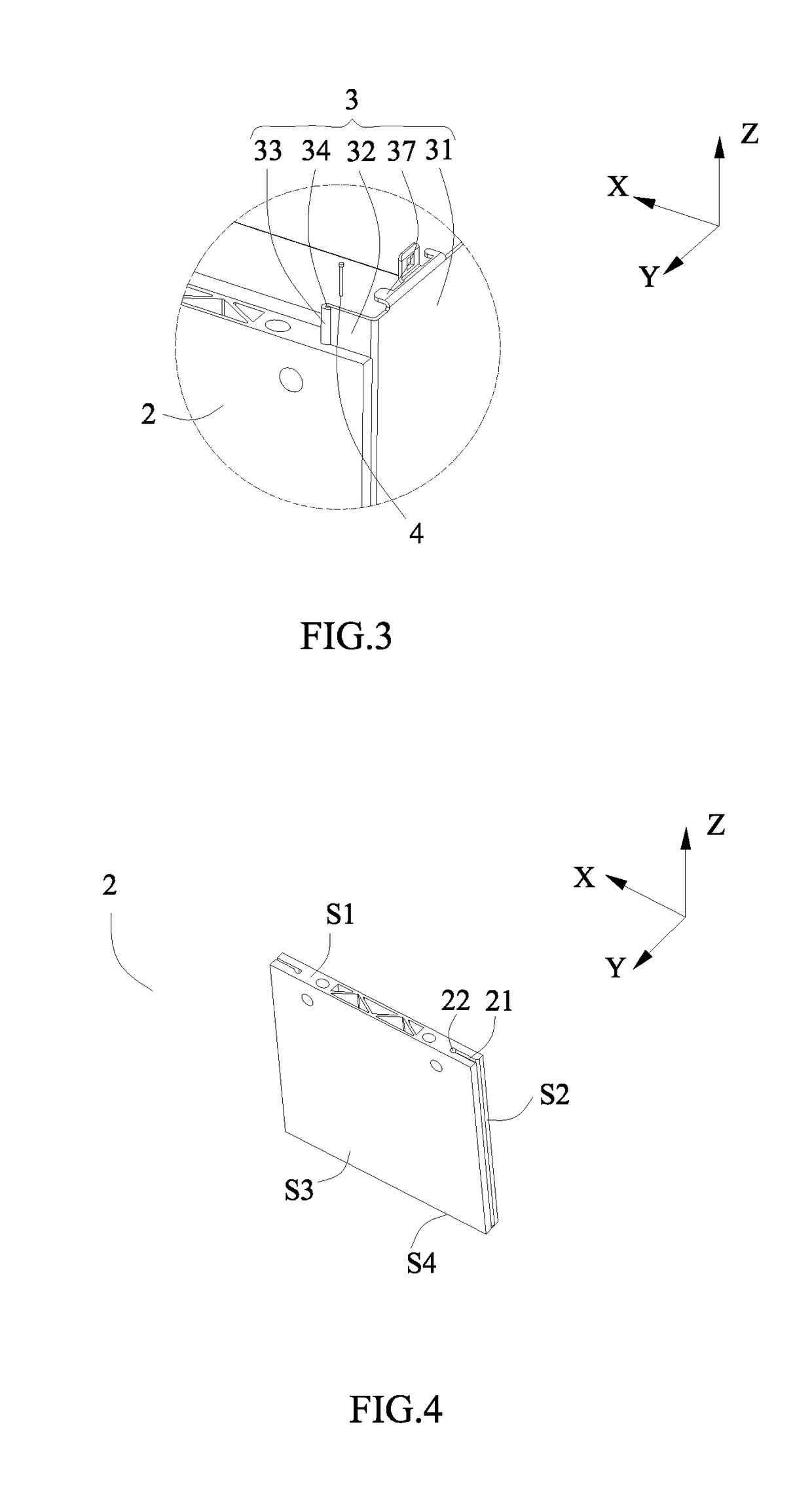
[0049]Referring to FIG. 1 to FIG. 11, a battery module according to the present disclosure comprises: a battery group 1 including a plurality of batteries 11 arranged in a Y direction; two end plates 2 respectively positioned at two ends of the battery group 1 in the Y direction; and two side plates 3 respectively positioned at two ends of the battery group 1 in a X direction. Each end plate 2 has X direction groove portions 21 respectively formed to two ends of the end plate 2 in the X direction. Each side plate 3 has a body portion 31 positioned at one of the two ends of the battery group 1 in the X direction; and inserting portions 32 respectively extending from two ends of the body portion 31 in the Y direction toward the X direction. The inserting portions 32 of each side plate 3 are respectively inserted into the corresponding X direction groove po...


PUM


Abstract

The present disclosure provides a battery module, which comprises a battery group, two end plates and two side plates. Each end plate has X direction groove portions respectively formed to two ends of the end plate in the X direction. Each side plate has: a body portion positioned at one of the two ends of the battery group in the X direction; and inserting portions respectively extending from two ends of the body portion in the Y direction toward the X direction. The inserting portions of each side plate are respectively inserted into the corresponding X direction groove portions of the end plates to limit relative movement between each side plate and the end plates in the Y direction to make each side plate and the end plates fixed and connected. Strength of the battery module is improved and the possibility in connection failure of the battery module is reduced.

Description

REFERENCE TO RELATED APPLICATIONS[0001]The present application claims priority to Chinese patent application No. CN201710339779.3, filed on May 15, 2017, which is incorporated herein by reference in its entirety.FIELD OF THE PRESENT DISCLOSURE[0002]The present disclosure relates to the field of battery technology, and particularly relates to a battery module.BACKGROUND OF THE PRESENT DISCLOSURE[0003]In the assembling process of a battery module, batteries, two surfaces of which have been coated with adhesives, are sequentially stacked, two end plates are respectively placed to two ends of the stacked batteries and two side plates are respectively placed to two sides of the stacked batteries, the two end plates and the two side plates together enclose the stacked batteries to form a battery module. In order to ensure the anti-vibration stability of the battery module, it needs to respectively coat enough quantity of adhesives on the two surfaces of each battery, adjust a size of the ...

Claims


Application Information

Patent Timeline
IPC IPC(8): H01M2/10H01M50/209
CPCH01M2/1077H01M2220/20H01M50/209H01M10/658Y02E60/10
Inventor ZHU, BANGYINGYU, FENG
Owner CONTEMPORARY AMPEREX TECH CO
Learn More