
Device and method for measuring the properties of hay using near infrared spectroscopy on a large square baler

a technology of near infrared spectroscopy and baler, which is applied in baling, agriculture tools and machines, instruments, etc., can solve the problems of inconsistent contact, limit the accuracy of nirs to reflective properties, and limit the placement of nirs sensors in the hay pickup area, so as to improve the accuracy

Active Publication Date: 2018-11-22
HARVEST TEC
View PDF2 Cites 13 Cited by
  • Summary
  • Abstract
  • Description
  • Claims
  • Application Information

AI Technical Summary

Benefits of technology

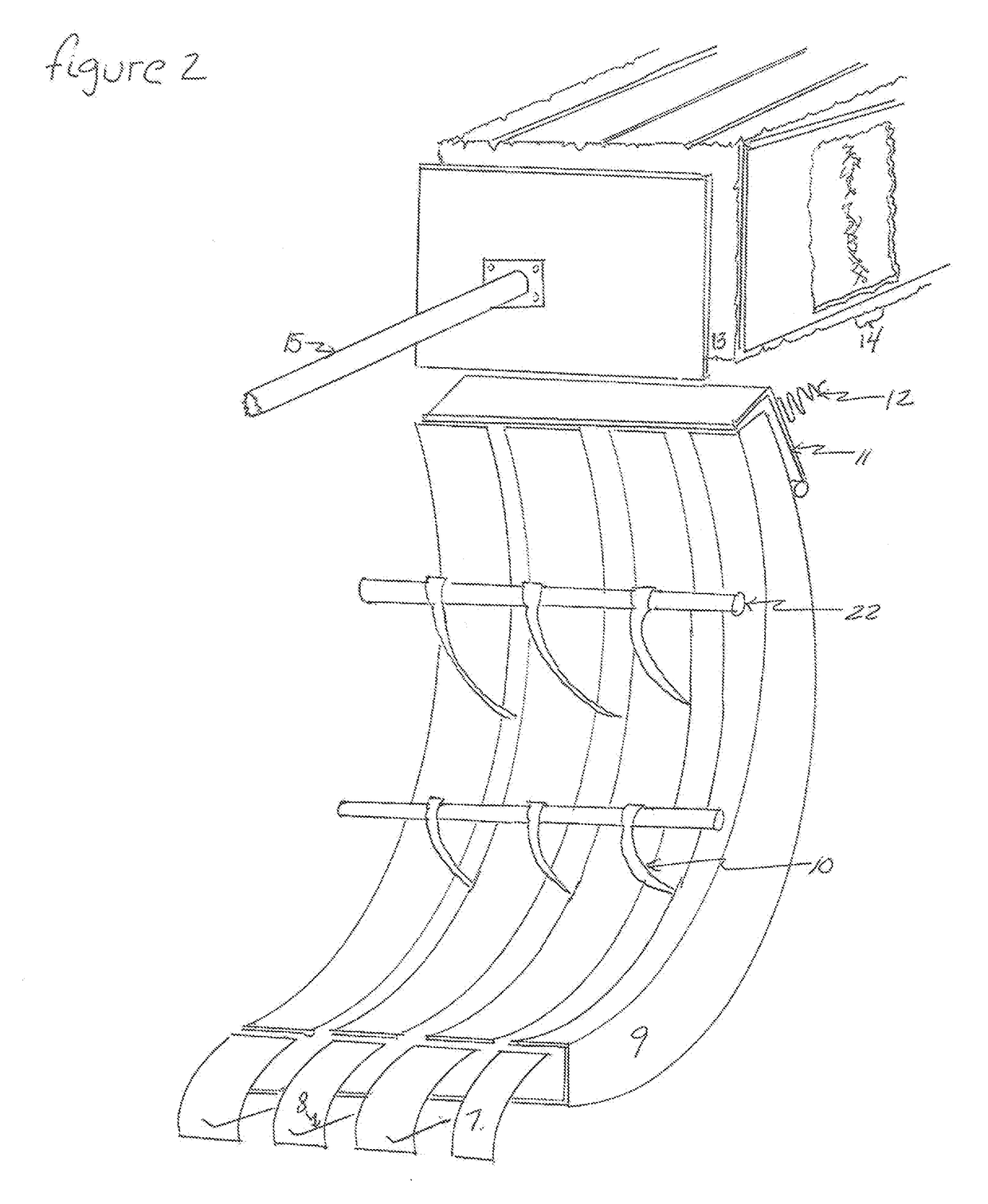
The present invention provides a way to get consistent readings from near infrared spectrographic sensors (NIRS) by averaging readings from multiple sensors placed near the top of a large square baler. The device also involves mounting the NIR sensors on the sides or bottom of the re-compression chamber to get accurate readings on the quality of constituents like net energy, dry matter digestibility, acid detergent fiber, neutral detergent fiber, protein, and moisture.

Problems solved by technology

The emitter light and reflective measuring equipment in a portable NIRS sensor has a maximum diameter of four inches which limits the accuracy of the NIRS to the reflective properties of measuring a small area of a somewhat non-uniform surface.
In the areas of the baler that are upstream to the pre-compression chamber, the limitation to placing NIRS sensors in the hay pickup area is due to interference between the NIRS sensors and pick-up mechanism.
Also, in placing the NIRS sensors in the pickup area would result in inconsistent contact with the hay being sampled as the pickup teeth bring the hay up into the baler in bunches as the rows of teeth grab the hay.
Located the NIRS sensors on the side, top or bottom of the formed bale would result in limited readings since the bale moves at a rate of under 3 inches per second after it is compacted in the main chamber.

Method used


Image

  • Device and method for measuring the properties of hay using near infrared spectroscopy on a large square baler
  • Device and method for measuring the properties of hay using near infrared spectroscopy on a large square baler
  • Device and method for measuring the properties of hay using near infrared spectroscopy on a large square baler

Examples


Embodiment Construction

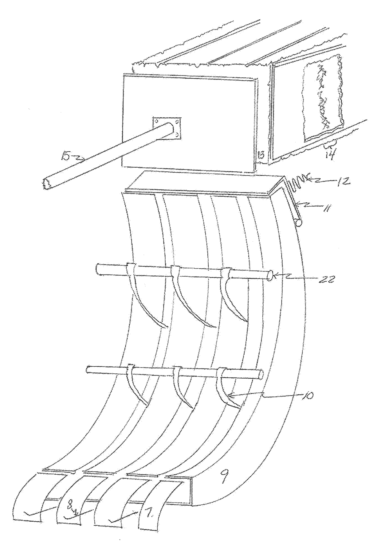
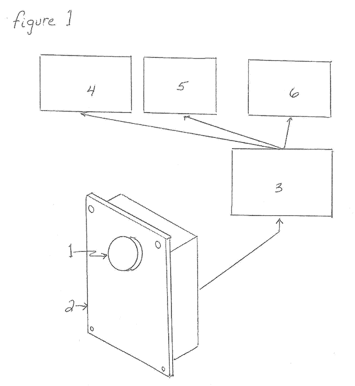
[0019]Near infra-red spectroscopy is read from a sensor by emitting a light thru a lens 1, FIG. 1, and reading the reflection of that light back thru the same lens 1 that is mounted on a sensor enclosure 2. The sensor enclosure also houses a power supply delivering DC power to the light and recording the reflective values taken from the light. The level of reflection is then sent as a message to a processor which alternatively could be housed separately or within the sensor enclosure 2. The processor has a software file with the expected values of reflection compared to a level of quality constituents including: net energy, in vitro dry matter digestibility, acid detergent fiber, neutral detergent fiber, protein and moisture. After the comparison is completed, the processor 3 averages multiple readings communicating the value to a display 4. Alternatively, the processor can communicate the values to a bale tagger 5 or a telemetry module 6 which will communicate the values to a remot...


PUM


Abstract

A DEVICE AND METHOD COMPRISING A LARGE SQUARE BALER WITH A PRE-COMPRSSION CHAMBER THAT ACCUMULATES HAY AND MOVES IT INTO THE COMPRESSION CHAMBER, ONE OR MORE NEAR INFRARED SPECROCOPY (NIRS) SENSORS MOUNTED NEAR THE TOP OF THE PRE-COMPRESSION CHAMBER, A MEANS TO READ INPUTS FROM THE SENSORS ONLY WHEN THE STUFFER FORKS ARE MOVING HAYFROM THE PRE-COMPRESSION CHAMBER INTO THE MAIN CHAMBER AND A PROCESSOR TO AVERAGE MULTIPLE READINGS FROM THE NIRS SENSORS FROM THAT INTEVAL.

Description

CROSS REFERENCE TO RELATED APPLICATION[0001]This application is a continuation in part of pending U.S. patent application Ser. No. 13 / 906,971 filed May 31, 2013 which is hereby incorporated by reference.STATEMENT REGARDING FEDERALLY SPONSORED RESEARCH OR DEVELOPMENT[0002]Not applicable.REFERENCE TO A MICROFICHE APPENDIX, IF ANY[0003]Not applicable.BACKGROUND OF THE INVENTION1. Field of Invention[0004]The present invention relates, generally, to crop harvesting apparatus and methods. Particularly, the invention relates to hay harvesting systems, apparatus and methods. The present invention is most particularly suitable for use in and for large rectangular (often called “square”) hay balers.2. Background Information[0005]The term “hay” usually applies to crops of alfalfa or a variety of grass that is harvested by a baler that compacts the loose crop into units that can be handled or transported and are normally referred to as “bales”. Bales are fed primarily to ruminant animals includ...

Claims


Application Information

Patent Timeline
IPC IPC(8): A01F15/08G01N21/359G01N21/3563G01N21/3554A01F15/10
CPCA01F15/0825G01N21/359G01N21/3563A01F15/042A01F15/101G01N2201/12A01F2015/102G01N21/3554G01N2021/8466
Inventor ROBERTS, JEFFREY S.
Owner HARVEST TEC
Learn More