Seat structure and chair

a seat and chair technology, applied in the field of chairs, can solve the problems of not being able to configure one piece of mesh fabric, not being able to meet the needs of everyone, etc., and achieve the effects of overcoming the uncomfortable feeling of users, convenient back configuration, and simple structur

Active Publication Date: 2018-11-22
UE FURNITURE CO LTD
View PDF26 Cites 8 Cited by
  • Summary
  • Abstract
  • Description
  • Claims
  • Application Information

AI Technical Summary

Benefits of technology

[0007]To overcome the shortcomings of the above-mentioned prior art, the present invention provides a seat structure and its application on chair which is simple in structure, aesthetically pleasing in appearance, and convenient in configuring the back and the seat of a chair as a whole with one piece mesh fabric, meanwhile it's able to lift the chair seat up when the chair back is leaning rearward. The seat structure can be used by different people and people of different weights. It overcomes the uncomfortable feeling of the user as the user has to apply great enough waist strength to make the seat of prior art raised as a whole, thus increasing comfort for different human body. Besides, throughout the process, any user can easily lean up and get back up and finds his / her comfort points in different positions.

Problems solved by technology

Due to its complex design of its overall structure, the user needs to apply enough force rearward, therefore it's not suitable for everybody.
Moreover, looking from aesthetic aspect, this kind of chair does not meet the needs of modern streamlined aesthetic, furthermore, it is not convenient to configure one piece mesh fabric that connects the back and the seat of a chair into a whole, instead, mesh fabric for the chair back and mesh fabric for the chair seat have to be configured separately.

Method used


Image

  • Seat structure and chair
  • Seat structure and chair
  • Seat structure and chair

Examples


embodiment 1

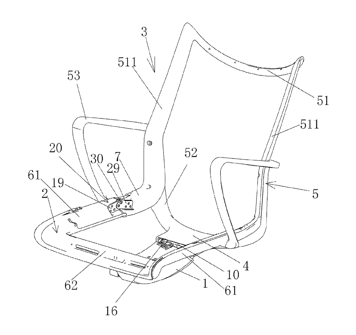
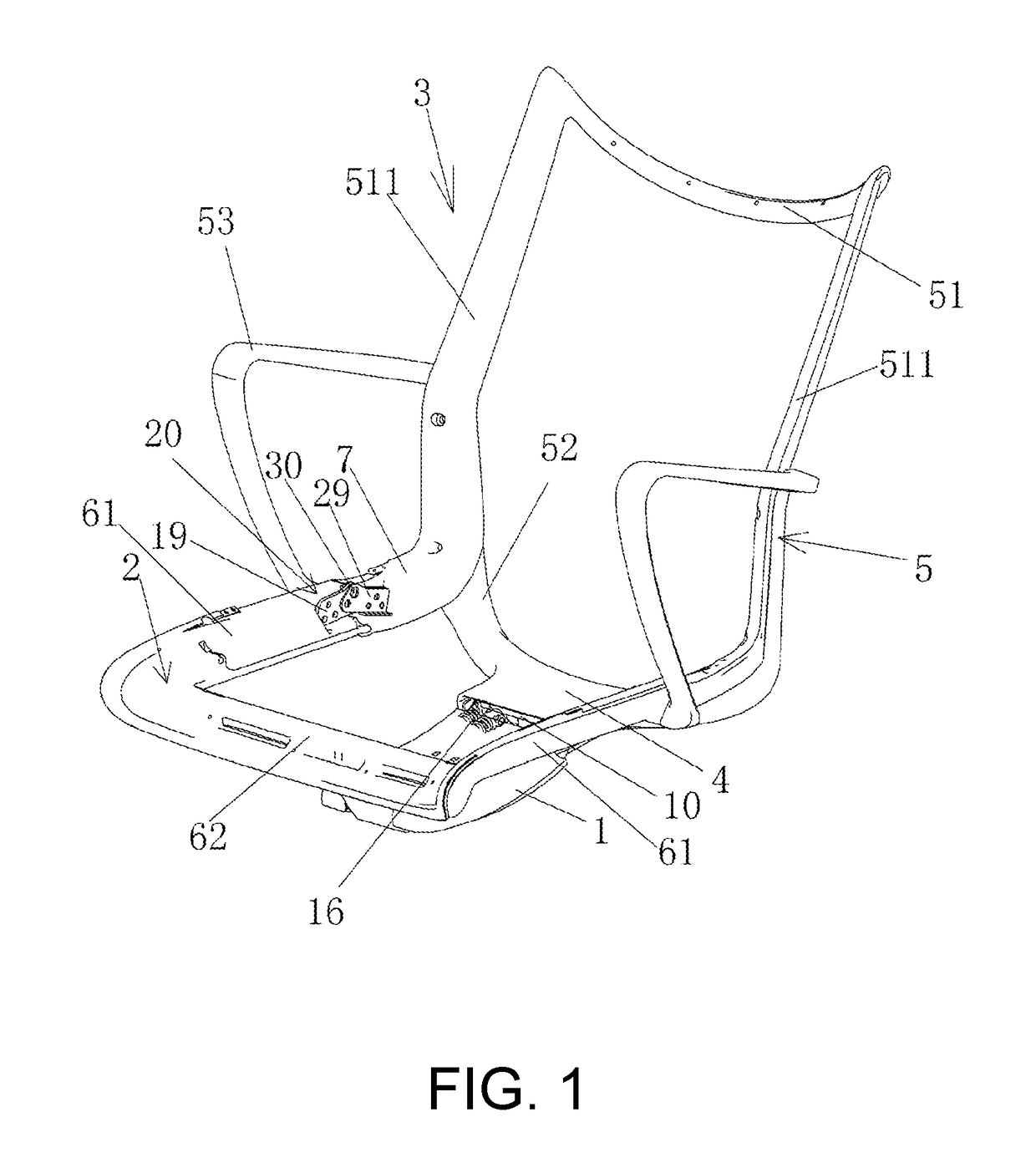
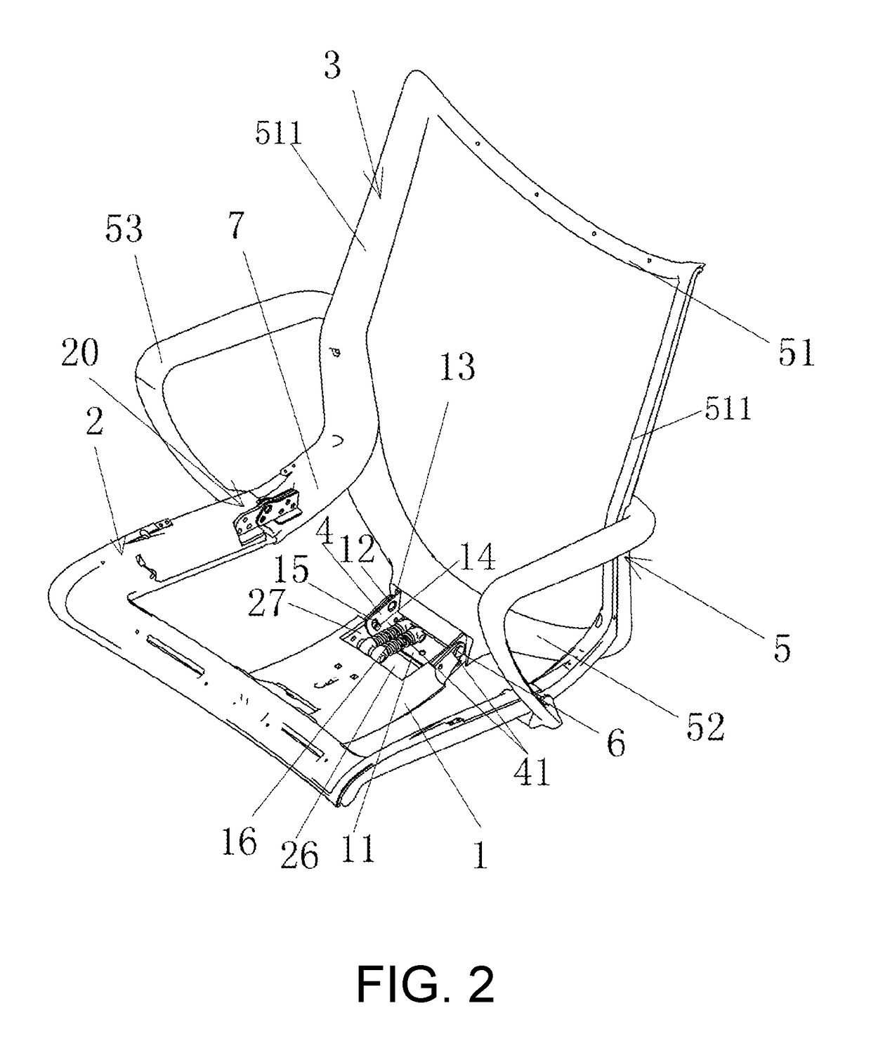
[0064]A seat structure in the embodiment shown in FIG. 1, FIG. 2, comprising:

[0065]Base 1, configured to be the chair base assembly; metal base is preferred for base 1; the chair base assembly (not shown) includes supporting column, a plurality of supporting legs extending radially from the lower end of the supporting column and casters supporting the leg ends. Said supporting column can be an air rod.

[0066]Seat support 2. Seat support 2 is installed above base 1 and remains approximately parallel with base 1, wherein seat support 2 has rotary connection with the front end of base 1 through a transition link 8. Said seat support 2 comprises two bilaterally symmetrical supporting bars 61. The front parts of the two supporting bars 61 are connected as a whole through cross bar 62, wherein cross bar 62 has rotary connection with the front part of base 1 through transition link 8. The font end of seat support 2 is bending and extending downward and rearward into human body sitting posit...

embodiment 2

[0082]In the embodiment shown in FIG. 9, FIG. 10, FIG. 11:

[0083]A seat structure comprising:

[0084]Base 1, configured to be the chair base assembly; base 1 presents a Y shape.

[0085]Seat support 2, which is s installed above base 1; the front end of seat support 2 is bending and extending downward and rearward into human body sitting position structure, and seat support 2 has rotary connection with base 1 in a frame structure.

[0086]Switch part 22, which is located between seat support 2 and base 1, wherein both ends of switch part 22 have rotary connection with the front part of seat support 2 and the front part of base 1 respectively.

[0087]Chair back assembly 3, which has rotary connection with the rear part of base 1 through pivot 6.

[0088]Lever driving member 7, which is linked between chair back assembly 3 and seat support 2. When chair back assembly 3 turns rearward from the initial position, seat support 2 is lifted up and moved rearward by lever driving member 7; when chair back...

embodiment 3

[0100]the present embodiment is substantially the same as in embodiment 1 in terms of the relationship between the composition and the structure of the lever driving member, the chair back assembly, the seat support, the transition link and the base. The main difference between this embodiment and embodiment 1 is that, as shown in FIGS. 16-25, reset spring 71 is installed longitudinally between chair back assembly 3 and base 1, to be more specific, reset spring 71 is configured in a position closer to the front than pivot 6, which means the reset spring is completely hidden in the inner space of the base. Thus, the height space inside the base can be fully utilized, and the exterior of the seat will not be protruded by the arrangement of the reset spring, nor will it cause damage to the appearance.

[0101]The longitudinal configuration is not strictly defined as longitudinal, and does not necessarily mean that the central line of reset spring 71 coincides with the plumb line. In a bro...


PUM


Abstract

A seat structure comprises a base configured to be a chair base assembly; a seat support located above the base, wherein a front part of the seat support has rotary connection with the front part of the base through a transition link; a chair back assembly having rotary connection with a rear part of the base through a pivot; a lever driving member linked between the chair back assembly and the seat support, and having rotary connection with a rear part of the seat support, wherein the lever driving member and the seat support are approximately on the same surface. When the chair back assembly rotates rearward around the pivot from the initial position, the rear part of the seat support is raised diagonally to the rear through the lever driving member, meanwhile the transition link and the front part of the seat support are pulled up.

Description

CROSS-REFERENCE TO RELATED APPLICATION[0001]This is a continuation of International Application No. PCT / CN2017 / 100291, filed on Sep. 1, 2017, which claims the priority benefits of China Application No. 201621081836.X, filed on Sep. 1, 2016 and China Application No. 201621368953.4, filed on Dec. 5, 2016. The entirety of each of the above-mentioned patent applications is hereby incorporated by reference herein and made a part of this specification.BACKGROUNDTechnical Field[0002]This invention relates to the technical field of chair, swivel chair, office chair, etc., in particular to a seat structure and chair.Description of Related Art[0003]Swivel chair chassis, also known as swivel chair tray, is an important component under the seat cushion. The lift and fall of the seat cushion as well as the tilt angle adjustment of the chair back all rely on the chassis to realize.[0004]In the prior art, there is already a device synchronizing the back and the seat. For example, the Chinese Paten...

Claims


Application Information

Patent Timeline
Patent Type & Authority Applications(United States)
IPC IPC(8): A47C1/032
CPCA47C1/03272A47C1/03255A47C3/026A47C7/443A47C1/03261A47C7/02A47C7/40A47C7/14A47C7/44A47C1/036A47C1/03274A47C7/282A47C7/024Y10S297/07
Inventor JIN, MINGHUAXIA, JINGZHIRUAN, ZHENGFU
Owner UE FURNITURE CO LTD
Why Eureka
Try Eureka