
Systems, methods, and articles for laser marking machine-readable symbols

a laser marking and machine-readable technology, applied in the field of laser marking machine-readable symbols, can solve problems such as slowness and imprecise along the edges

Active Publication Date: 2018-11-22
DATALOGIC IP TECH
View PDF0 Cites 11 Cited by
  • Summary
  • Abstract
  • Description
  • Claims
  • Application Information

AI Technical Summary

Benefits of technology

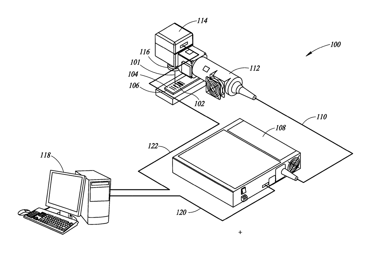
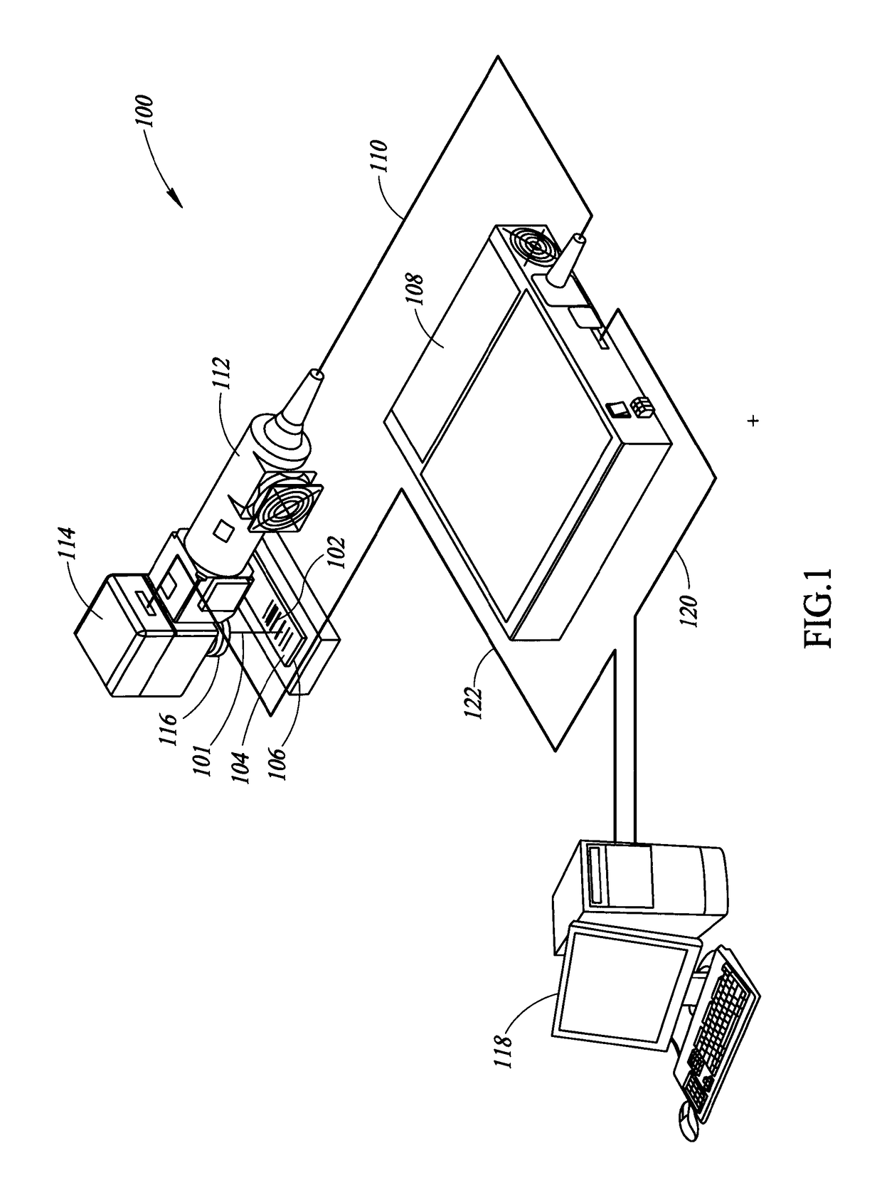
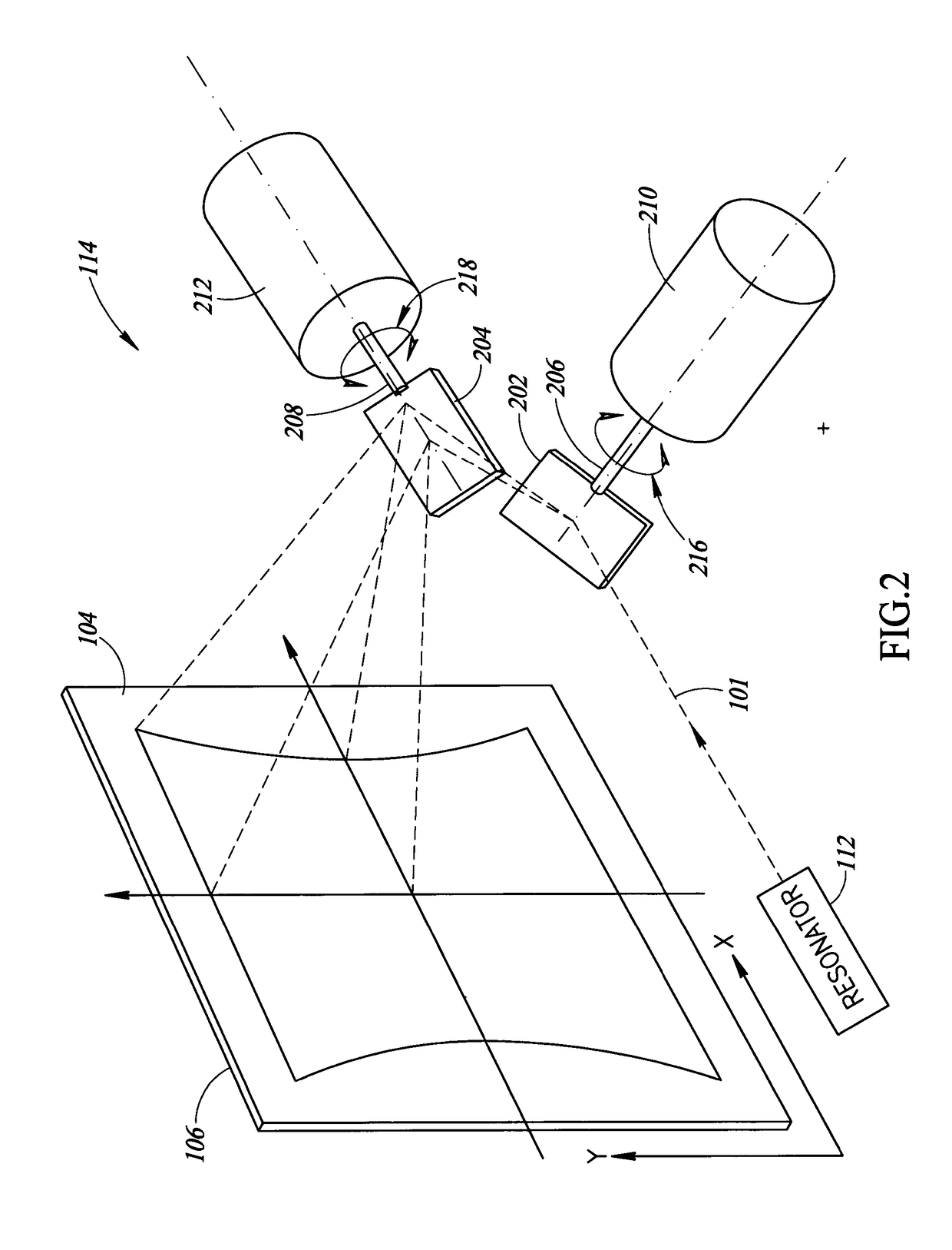
The patent describes a method and system for generating a laser beam path to mark a surface of an object with a machine-readable symbol. The system includes a processor and a non-transitory processor-readable medium with instructions for the processor. The method involves obtaining machine-readable symbol data, grouping the symbol data into first and second type modules, and generating a bounded area fill pattern that includes an outer boundary path line for each module. The laser beam path is then generated to direct the laser beam to traverse each path line in the pattern. The technical effect of this invention is to provide a more efficient and precise method for generating a laser beam path to mark an object with a machine-readable symbol.

Problems solved by technology

These filling methods provide a uniform surface treatment but are slow and imprecise along the edges, since a scan head controlling the laser must make a discontinuous path, and the laser source must be continuously turned on and off to avoid marking during the movement from the end of one stroke to the beginning of a subsequent stroke.

Method used


Image

  • Systems, methods, and articles for laser marking machine-readable symbols
  • Systems, methods, and articles for laser marking machine-readable symbols
  • Systems, methods, and articles for laser marking machine-readable symbols

Examples


Embodiment Construction

[0040]In the following description, certain specific details are set forth in order to provide a thorough understanding of various disclosed embodiments. However, one skilled in the relevant art will recognize that embodiments may be practiced without one or more of these specific details, or with other methods, components, materials, etc. In other instances, well-known structures associated with the various embodiments have not been shown or described in detail to avoid unnecessarily obscuring descriptions of the embodiments.

[0041]Unless the context requires otherwise, throughout the specification and claims that follow, the word “comprising” is synonymous with “including,” and is inclusive or open-ended (i.e., does not exclude additional, unrecited elements or method acts).

[0042]Reference throughout this specification to “one embodiment” or “an embodiment” means that a particular feature, structure or characteristic described in connection with the embodiment is included in at lea...


PUM

PropertyMeasurementUnit
wavelengthsaaaaaaaaaa

Abstract

Systems and methods for generating machine-readable symbols on surfaces of objects using laser marking systems and processes. A specialized contour fill pattern for a laser beam path may be used that combines modules of a machine-readable symbol into bounded blocks or islands according to adjacencies and / or according to role (e.g., finder pattern, timing pattern, encoded payload data). In some implementations, the islands of modules may be filled using a laser beam path that traverses contour path lines from inner path lines to outer path lines. Once the islands have been generated during pre-processing, they are sorted to reduce the required time for the laser to “jump” (i.e., move with the laser turned off) from one island to a subsequent island to be filled. A filling pattern for bounded areas with sharp corners (e.g., squares, rectangles) may be simplified by rounding corners to optimize speed while maintaining suitable marking quality.

Description

BACKGROUNDTechnical Field[0001]The present disclosure relates generally to laser marking of machine-readable symbols.Description of the Related Art[0002]Machine-readable symbols encode information in a form that can be optically read via a machine-readable symbol reader or scanner. Machine-readable symbols take a variety of forms, the most commonly recognized form being the linear or one-dimensional barcode symbol. Other forms include two-dimensional machine-readable symbols such as stacked code symbols, and area or matrix code symbols. These machine-readable symbols are typically made of patterns of high and low reflectance areas. For instance, a one-dimensional barcode symbol may comprise a pattern of black bars on a white background. Also for instance, a two-dimensional symbol may comprise a pattern of black marks (e.g., bars, squares or hexagons) on a white background. Machine-readable symbols are not limited to being black and white, but may comprise two other colors, and / or ma...

Claims


Application Information

Patent Timeline
Patent Type & Authority Applications(United States)
IPC IPC(8): B41J2/315
CPCB41J2/315G06K1/126G06K15/1228B23K26/0665B23K26/08B41J2/442B23K26/082B08B7/0042B44C1/228
Inventor GREGGIO, ROBERTO
Owner DATALOGIC IP TECH
Learn More