Architected material design for seismic isolation

a material design and seismic isolation technology, applied in the direction of shockproofing, bridges, mechanical equipment, etc., can solve the problems of limiting the maximum allowed lateral displacement, affecting the seismic isolation effect, and limiting the dimensions of the isolator

Inactive Publication Date: 2018-11-22
RGT UNIV OF CALIFORNIA
View PDF9 Cites 10 Cited by
  • Summary
  • Abstract
  • Description
  • Claims
  • Application Information

AI Technical Summary

Benefits of technology

[0025]Various objects, features, aspects and advantages of the inventive subject matter will become more apparent from the following detailed description of preferred embodiments, along with the accompanying drawing figures in which like numerals represent like components.

Problems solved by technology

A large number of the prior art patents for seismic isolators or supports have never been implemented in actual structures because of the high costs associated with their implementation, (see e.g., US Patent Application No. 2006 / 0174555), or because they are too complex, or not reliable enough and require excessive maintenance.
Rubber compounds with high levels of damping, however, may be severely affected by creep phenomena under large vertical loads.
As is known in the art, (see e.g., U.S. Pat. No. 8,789,320) a drawback of a typical steel reinforced elastomeric bearing is its susceptibility to instability phenomena, which limits the maximum allowed lateral displacement and constraints the dimensions of the isolator.
Increase of the height of the rubber may be considered to enhance the lateral displacement capability, but reduces stability and vertical stiffness of the isolator.
Finally, as is known in the art, a drawback of these bearings is associated with wearing of the material.
As described in U.S. Pat. No. 6,107,389, the rubber creeps over time, resulting in poor long-term endurance.
The friction during the sliding movement of the intermediate elements with respect to each other causes also problems to the isolators, as described in U.S. Pat. No. 8,011,142.
Also, friction forces cause wear problems of the sliding materials, which results in a reduced service life of the isolator if complex lubrication systems are not provided.
Application No. 2014 / 0026498A1), these conventional sliding materials do not have adequate wear resistance and are subjected to continuous wearing during in service movements of a structure.
A further drawback of sliding material such as PTFE or UHMWPE is the dependency of their friction characteristics on sliding velocity, contact pressure (as disclosed in Quaglini at al.
This dependency causes variations of the friction properties during shaking events that may alter the seismic performance of the isolator.
This means that the isolator may no longer function as intended in its application.
A drawback of these materials is their sensitivity to even minor inaccuracies and defects in the bearing components, which can lead to significant reduction of the bearing capacity, as described in U.S. Pat. No. 8,371,075.
One common drawback to all state-of-art isolators is the cost of the prototype and production testing to assess their seismic performance.
Any change of geometry and size of the isolators requires additional tests, which affect the final cost of the delivered product, well beyond the actual material and labor production cost.
Full scale seismic isolators testing are generally performed in very expensive dedicated facilities (as disclosed in Benzoni, G., Lomiento, G., Bonessio, N.
Even if the base seismic isolation approach has already gained recognition as an effective protection against earthquakes, its extensive application is limited by the drawbacks of existing isolators.

Method used


Image

  • Architected material design for seismic isolation
  • Architected material design for seismic isolation
  • Architected material design for seismic isolation

Examples


examples

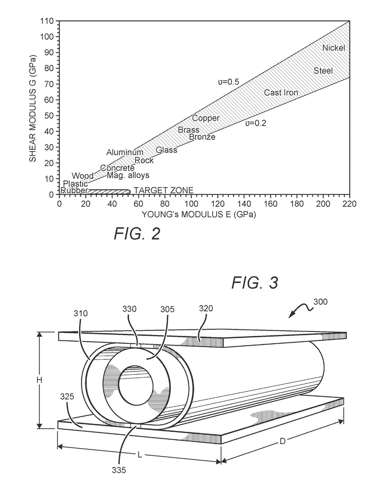
[0088]Numerical simulations are performed to assess the performance of the newly architected material. Because in the proposed cellular periodic material the mechanical properties (e.g., Young Modulus and Shear Modulus) of the unit cells' layers replicate on a large scale the properties of the unit cell, a numerical simulation of the unit cell was performed.

[0089]A finite element model of a particular embodiment of the single cell (embodiment FIG. 4a) is presented under a vertical pressure of 20 MPa and for lateral deflections resulting in shearing forces of 20%-30% of the structure weight. This load scenario may represent the behavior for Maximum Credible Earthquakes.

[0090]A parametric analysis based on the variation of some geometrical parameters of the unit cell is performed in order to show how the mechanical property of the architected material can be optimized by changing the geometry of unit cell.

[0091]A set of values for shells thickness (S1=0.1 mm, S2=0.2 mm, S3=0.4 mm), a ...


PUM


Abstract

Seismic protection materials are derived from assemblages of unit cells, where each of the cells has a core, one or more shells disposed about the core, and rigid plates bounding the shells. The cores limit relative vertical movement between the plates, and the shell(s) limit relative lateral motion between the plates. Uncompressed cores are preferably substantially spherical or cylindrical, and can be solid or hollow. Unit cells can be aligned in same or different directions, both within a given layer of cells, and in different layers of cells. Assemblages can have any suitable overall shape and size, depending upon application, and for example can support objects ranging from table top equipment to large buildings and bridges.

Description

[0001]This application claims the benefit of priority to U.S. Provisional Patent Application No. 62 / 173,637, filed Jun. 10, 2015, and PCT Patent Application Number PCT / US16 / 36707, filed Jun. 9, 2016, which are incorporated by reference herein in their entirety.FIELD OF THE INVENTION[0002]The field of the invention is seismic isolation devices for buildings, bridges and other structures.BACKGROUND[0003]The background description includes information that may be useful in understanding the present invention. It is not an admission that any of the information provided herein is prior art or relevant to the presently claimed invention, or that any publication specifically or implicitly referenced is prior art.[0004]Seismic isolators may be used on structures for safety and economic reasons. Seismic isolation overcomes the limitations of traditional seismic design, which is based on designing and detailing a structure to provide sufficient ductility and energy-absorption capacity. While ...

Claims


Application Information

Patent Timeline
Patent Type & Authority Applications(United States)
IPC IPC(8): E04H9/02E04B1/98E01D19/04
CPCE04H9/022E04B1/98E01D19/041E01D19/04F16F15/046F16F15/073
Inventor BONESSIO, NOEMIVALDEVIT, LORENZOLOMIENTO, GIUSEPPE
Owner RGT UNIV OF CALIFORNIA
Why Eureka
Try Eureka