Rare-earth Permanent Magnet-Forming Sintered Body, and Rare-earth Permanent Magnet obtained by Magnetizing said Sintered Body

a technology of permanent magnet and sintered body, which is applied in the direction of magnetic bodies, magnetic circuit rotating parts, magnetic circuit shapes/forms/construction, etc., can solve the problems of reducing the efficiency of magnets, increasing the gap between the stator and the rotor, and varying the orientation of easy-to-magnetize axes. to achieve the effect of reducing the cogging torqu

Active Publication Date: 2018-11-22
NITTO DENKO CORP
View PDF0 Cites 12 Cited by
  • Summary
  • Abstract
  • Description
  • Claims
  • Application Information

AI Technical Summary

Benefits of technology

[0020]In the present invention, easy-to-magnetize axes of magnet material particles in each of the end regions of the rare-earth permanent magnet-forming sintered body are oriented with a deviation from a polar-anisotropic orientation, as mentioned above, so that, even in the case where a plurality of permanent magnets each obtained by magnetizing the sintered body are arranged in a ring shape through an inter-end face gap, it becomes possible to enable a magnetic flux distribution in the vicinity of the inter-end face gap to come closer to a sinusoidal wave. This makes it possible to reduce cogging torque in a rotary electric machine using this permanent magnet.

Problems solved by technology

According to the description of the Patent Document 3, a magnet using a NdFeB-based material which is a magnet material containing a rare-earth substance has a problem that, in an orientation step of orienting easy-to-magnetize axes of the magnet material particles and a sintering step of sintering the magnet material particles, variation in the orientation and anisotropy in thermal expansion coefficient occur, thereby leading to variance in the orientations of the easy-to-magnetize axes after the sintering.
However, this configuration is required to increase the gap between the stator and the rotor.
Thus, there is a concern about a problem of degradation in magnet efficiency.
In the magnet unit as described in the Patent Documents 5 and 6, in which a plurality of pillar-shaped magnets each having an arc-shaped cross-section are arranged in a circular cylindrical shape, due to an inter-edge gap inevitably formed between opposed end faces of circumferentially-adjacent ones of the pillar-shaped magnets, a surface magnetic flux distribution is largely deviated from a sinusoidal-wave shape at a position of the inter-edge gap, so that it is difficult to sufficiently achieve the reduction of cogging torque.

Method used


Image

  • Rare-earth Permanent Magnet-Forming Sintered Body, and Rare-earth Permanent Magnet obtained by Magnetizing said Sintered Body
  • Rare-earth Permanent Magnet-Forming Sintered Body, and Rare-earth Permanent Magnet obtained by Magnetizing said Sintered Body
  • Rare-earth Permanent Magnet-Forming Sintered Body, and Rare-earth Permanent Magnet obtained by Magnetizing said Sintered Body

Examples


first embodiment

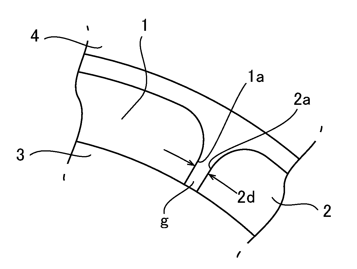
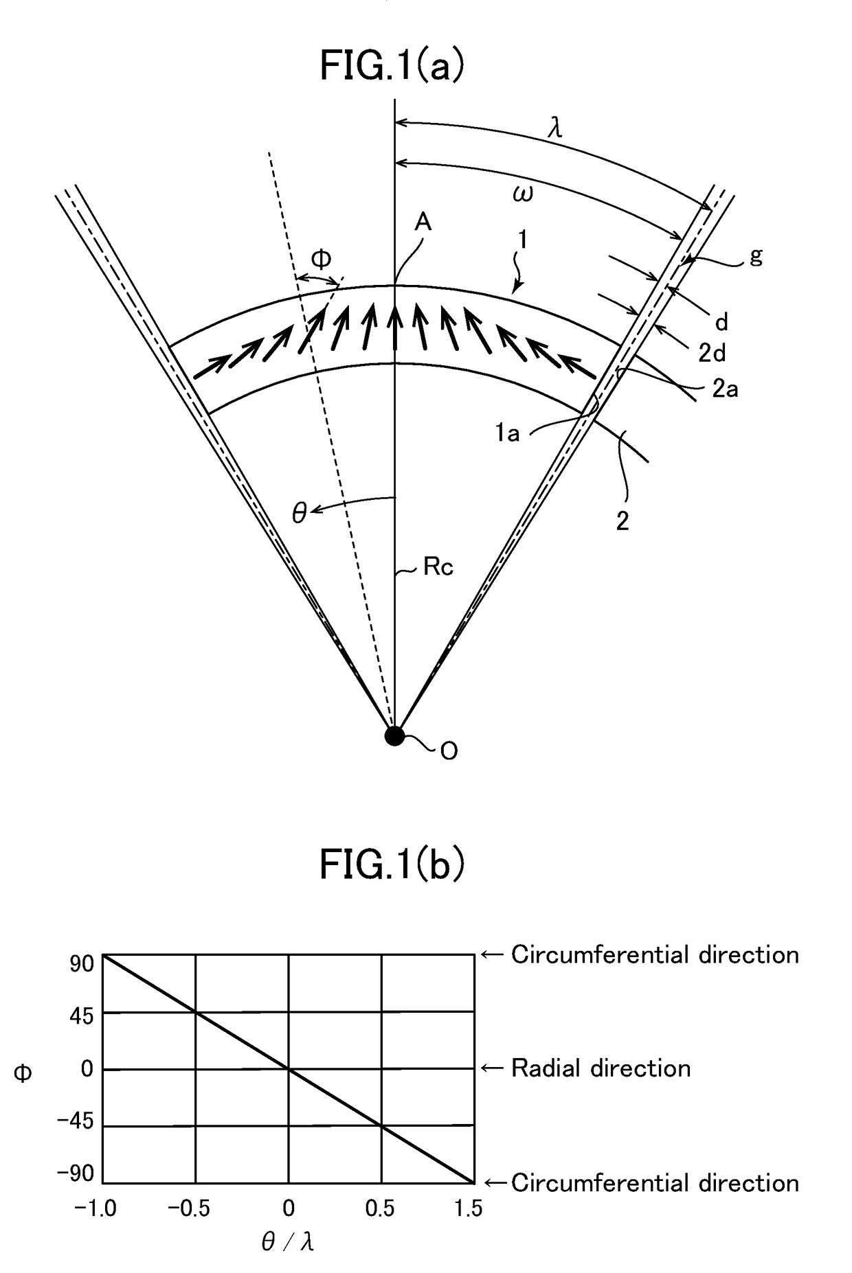
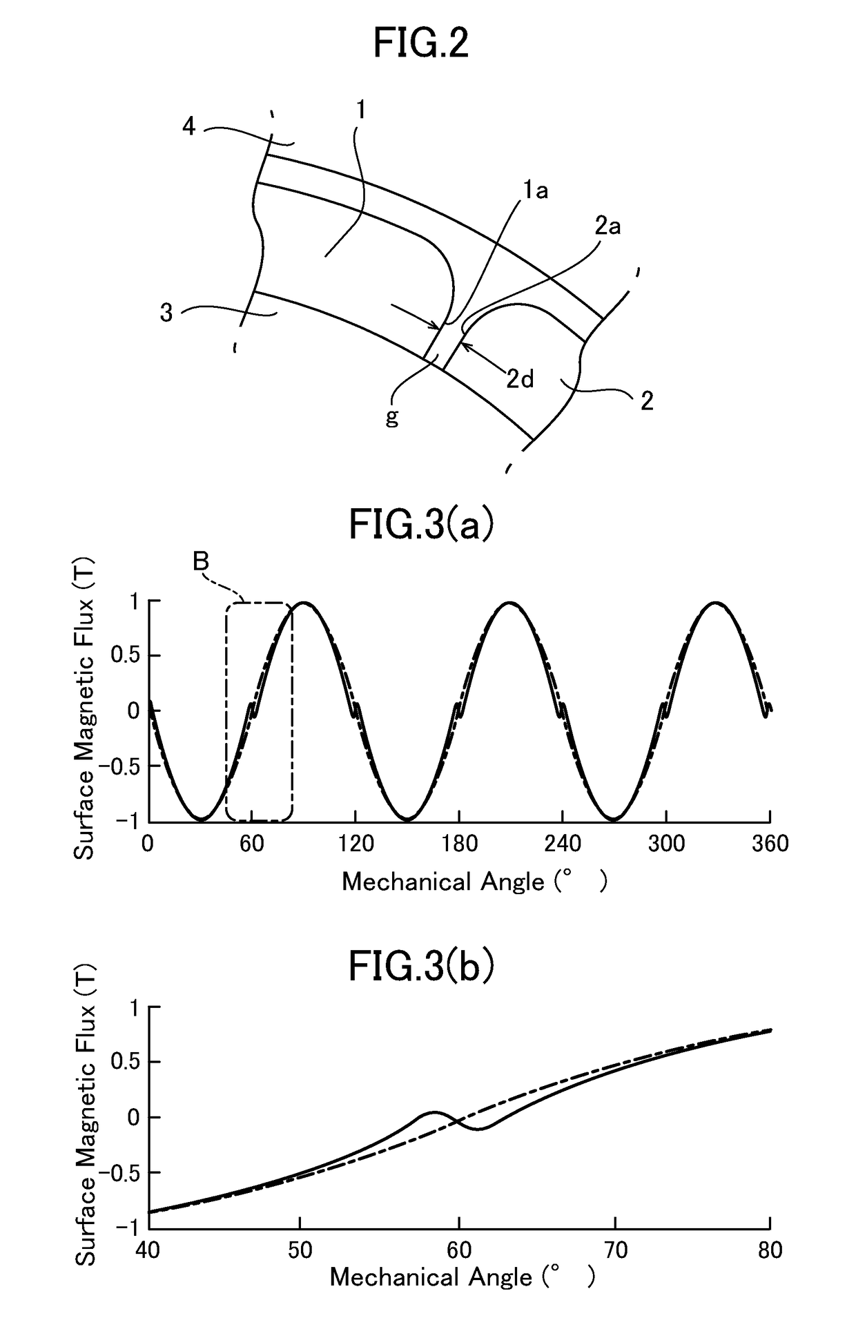
[0042]FIG. 4 depicts a segment magnet 11 for forming a 6-pole polar-anisotropic ring magnet, according to a first embodiment of the present invention. The segment magnet 11 is formed in the same basic shape as that of the segment magnet 1 depicted in FIG. 1(a), i.e., an arc shape having a curvature center at a point O, and disposed over a circumferential length of an angular range 2λ equivalent to one pole of the 6-pole polar-anisotropic ring magnet. The segment magnet 11 is disposed such that a gap g equivalent to the aforementioned angle 2d is formed with respect to a circumferentially-adjacent segment magnet 12. Thus, as previously mentioned with reference to FIG. 1(a), the circumferential length of the segment magnet 11 becomes an angular interval 2ω which is less than the angular range 2λ equivalent to one pole, by the angular range 2d.

[0043]In this embodiment, in the segment magnet 11, a region extending circumferentially inwardly from each of two end faces 11a of circumferent...

second embodiment

[0048]Except that, in the formula (4), m is set to (π / 2)−d+(Δ / ε), and n is set to 1, the second embodiment is exactly the same as the first embodiment. Here, Δ is an arbitrarily set constant. In this case, the magnetization direction Φ(θ) in each of the end region 13 is expressed by the following formula:

Φ(θ)=(1−ε)(90°−d)−[θ−(1−ε)ω](Δ / (εω))  (6)

[0049]The relationship between the angles θ and Φ of the segment magnet 11 according to the second embodiment in which the magnetization direction in each of the end regions 13 is set based on the formula (6) can be indicated by taking θ / λ and Φ, respectively, on the horizontal axis and the vertical axis, as depicted in FIG. 6. As can be seen from FIG. 6, in the segment magnet 11 according to the second embodiment, the magnetization direction angle in each of the end regions 13 linearly decreases in inverse proportion to an increase in the absolute value of the angle θ.

[0050]In the formula (6), A denotes a constant falling within the followin...

third embodiment

[0051]Except that, in the formula (4), each of m and n is a constant arbitrarily set in the range of greater than 1, the third embodiment is exactly the same as the first and second embodiments. In this case, the magnetization direction Φ(θ) in each of the end region 13 is expressed by the following formula:

Φ(θ)=(90°−d)θ / ω−m[(θ / ω)−(1−ε)]n  (7)

[0052]The relationship between the angles θ and Φ of the segment magnet 11 according to the third embodiment in which the magnetization direction in each of the end regions 13 is set based on the formula (7) can be indicated by taking θ / λ and Φ, respectively, on the horizontal axis and the vertical axis, as depicted in FIG. 7. As can be seen from FIG. 7, in the segment magnet 11 according to the third embodiment, the magnetization direction angle in each of the end regions 13 changes depending on the angle θ based on a power law.

[0053]Even in a region where Φ changes based on the formula (7) under the power law, there is an area having almost n...


PUM

PropertyMeasurementUnit
angleaaaaaaaaaa
curvature radiusaaaaaaaaaa
curvatureaaaaaaaaaa

Abstract

This invention provides for a rare-earth permanent magnet-forming sintered body having an integral sintered structure of magnet material particles containing a rare-earth substance. The integral sintered structure is formed in a three-dimensional shape having: a cross-section with a shape defined by a radially outer-side arc-shaped surface having a first curvature radius, a radially inner-side arc-shaped surface having a second curvature radius less than the first curvature radius and having an arc shape concentric with the outer-side arc-shaped surface; and a first end face and a second end face each of which is a radially-extending face along a virtual radial line extending from a curvature center of the arc shapes; and an axial length extending in a direction perpendicular to the cross-section.

Description

TECHNICAL FIELD[0001]The present invention relates to a rare-earth permanent magnet-forming sintered body having an integrally sintered structure of magnet material particles (particles of a magnet material) containing a rare-earth substance, and a rare-earth permanent magnet obtained by magnetizing the rare-earth permanent magnet-forming sintered body. Further, the present invention relates to a rotary electric machine, such as an electric motor or a power generator, comprising a rotor in which a plurality of rare-earth permanent magnets each obtained by magnetizing the rare-earth permanent magnet-forming sintered body are arranged on a circular outer peripheral surface of a rotor core thereof with a given gap between opposed end faces of circumferentially-adjacent ones of the rare-earth permanent magnets. In particular, the present invention relates to a rare-earth permanent magnet usable in a rotary electric machine having a rotor with surface-arranged permanent magnets, and suit...

Claims


Application Information

Patent Timeline
Patent Type & Authority Applications(United States)
IPC IPC(8): H01F1/08H02K1/27H02K1/02H01F41/02H01F7/02
CPCH01F1/086H02K1/2706H02K1/02H01F41/0253H01F7/02H01F13/00H02K1/27H02K15/03H01F41/0273
Inventor FUJIHARA, MAKOTOFUJIKAWA, KENICHISAITO, SHOICHIRO
Owner NITTO DENKO CORP
Why Eureka
Try Eureka