Fuel cell stack

a fuel cell and stack technology, applied in the direction of fuel cell details, fuel cells, electrochemical generators, etc., can solve the problems of inability to perform stably power generation, reactant gas cannot enter the end cell easily, and difficulty in continuing power generation, so as to improve the power generation stability of the fuel cell stack, prolong the product life, and reduce the quantity of stagnant water

Active Publication Date: 2018-11-29
HONDA MOTOR CO LTD
View PDF3 Cites 2 Cited by
  • Summary
  • Abstract
  • Description
  • Claims
  • Application Information

AI Technical Summary

Benefits of technology

[0007]The present invention has been made taking the above problem into account, and an object of the present invention of to provide a fuel cell stack in which it is possible to suppress stagnation of produced water at a deep end of a reactant gas discharge passage when the fuel cell stack is tilted.
[0013]In the fuel cell stack of the present invention, a plurality of reactant gas discharge passages are formed, and the reactant gas discharge passages are connected together by a connection channel. Therefore, when the fuel cell stack is tilted, it is possible to reduce the quantity of produced water (stagnant water) retained at the deep end of the reactant gas discharge passage of the stack body or prevent the produced water (stagnant water) from being retained at the deep end of the reactant gas discharge passage of the stack body. In the structure, it is possible to improve the power generation stability of the fuel cell stack. Further, since the quantity of the stagnant water is reduced, or no stagnant water is produced, it is possible to extend the product life of at least any of the electrolyte membrane, electrode catalyst, and the separator.

Problems solved by technology

As a result, since the pressure loss in the power generation cell positioned at the end in the stacking direction (end cell) is increased, the reactant gas cannot enter the end cell easily.
As a result, the power generation cannot be performed stably.
Therefore, continuation of the power generation may become difficult.
Further, since degradation of the electrolyte membranes, degradation of the electrode catalyst, and corrosion of the separators may occur due to the stagnant water retained in the cells, the product life of the fuel cell stack becomes short.

Method used


Image

  • Fuel cell stack
  • Fuel cell stack
  • Fuel cell stack

Examples


Embodiment Construction

[0022]Hereinafter, a preferred embodiment of a fuel cell stack of the present invention will be described with reference to the accompanying drawings.

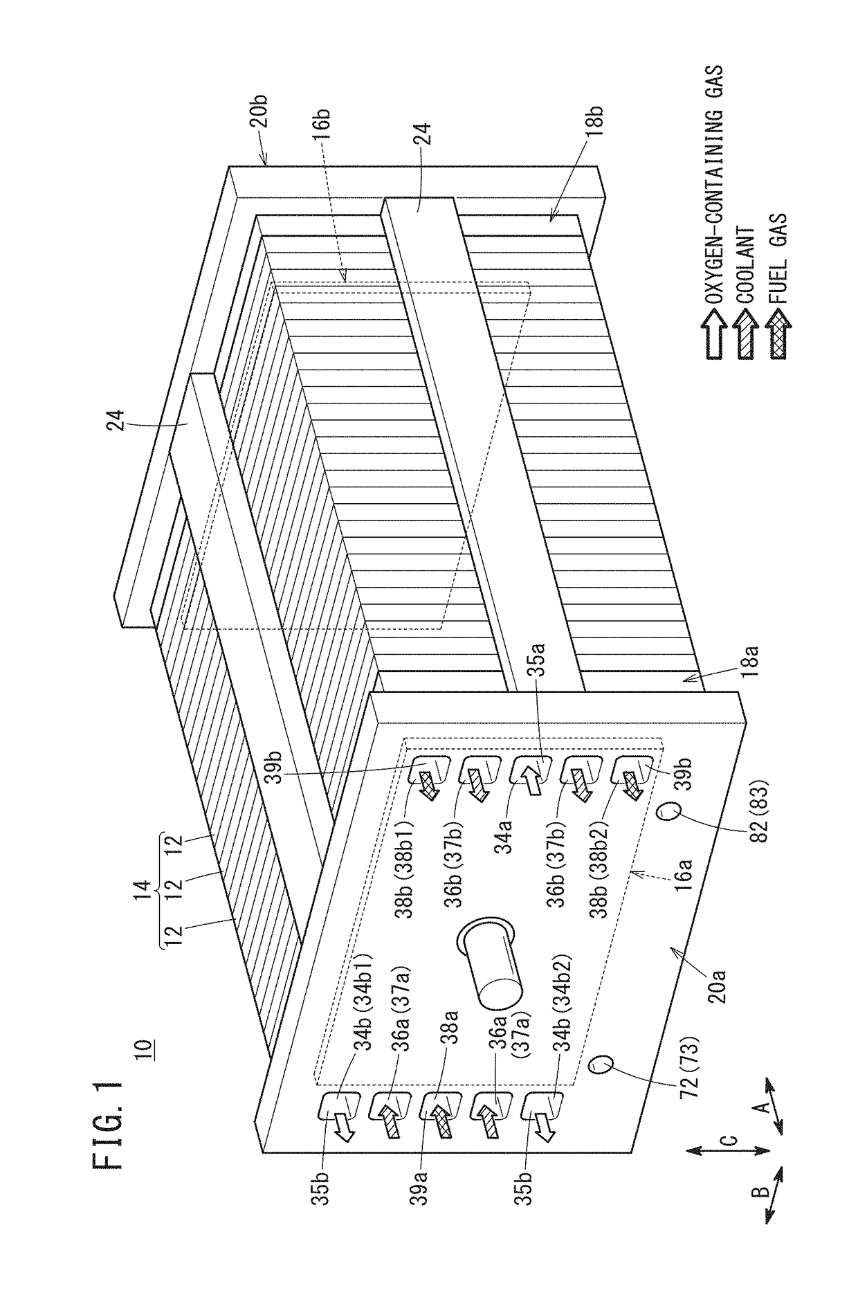
[0023]As shown in FIG. 1, a fuel cell stack 10 according to the embodiment of the present invention includes a stack body 14 formed by stacking a plurality of power generation cells 12 in a horizontal direction indicated by an arrow A or in a gravity direction indicated by an arrow C. For example, the fuel cell stack 10 is mounted in a fuel cell vehicle such as a fuel cell electric automobile (not shown).

[0024]At one end of the stack body 14 in the stacking direction indicated by the arrow A, a terminal plate (power collection plate) 16a is provided. An insulator 18a is provided outside the terminal plate 16a, and an end plate 20a is provided outside the insulator 18a. At another end of the stack body 14 in the stacking direction, a terminal plate 16b is provided. An insulator 18b is provided outside the terminal plate 16b, and an end ...


PUM

PropertyMeasurementUnit
heightsaaaaaaaaaa
pressure lossaaaaaaaaaa
concentrationaaaaaaaaaa

Abstract

A fuel cell stack includes a stack body of power generation cells stacked in a horizontal direction. An oxygen-containing gas flow field is formed in the fuel cell stack, for allowing an oxygen-containing gas to flow along an electrode surface of a membrane electrode assembly. A plurality of oxygen-containing gas discharge passages for discharging the oxygen-containing gas as a reactant gas pass through the fuel cell stack in a stacking direction of the power generation cells. Each of the oxygen-containing gas discharge passages is connected to an outlet. The plurality of oxygen-containing gas discharge passages are connected together by a first connection channel at an end opposite to the outlet.

Description

CROSS-REFERENCE TO RELATED APPLICATION[0001]This application is based upon and claims the benefit of priority from Japanese Patent Application No. 2017-103584 filed on May 25, 2017, the contents of which are incorporated herein by reference.BACKGROUND OF THE INVENTIONField of the Invention[0002]The present invention relates to a fuel cell stack.Description of the Related Art[0003]In general, a solid polymer electrolyte fuel cell employs a solid polymer electrolyte membrane. The solid polymer electrolyte membrane is a polymer ion exchange membrane. The fuel cell includes a membrane electrode assembly (MEA). The membrane electrode assembly is formed by providing an anode on one surface of the solid polymer electrolyte membrane, and providing a cathode on the other surface of the solid polymer electrolyte membrane.[0004]The membrane electrode assembly is sandwiched between separators (bipolar plates) to form a power generation cell (unit cell). A predetermined number of power generatio...

Claims


Application Information

Patent Timeline
Patent Type & Authority Applications(United States)
IPC IPC(8): H01M8/0258H01M8/2465H01M8/1004H01M8/1007H01M8/0284H01M8/0273
CPCH01M2008/1095H01M8/0258H01M8/2465H01M8/1004H01M8/1007H01M8/0284H01M8/0273H01M8/2483H01M8/242H01M8/04156Y02E60/50
Inventor SAKANO, MASAAKIMORIKAWA, HIROSHI
Owner HONDA MOTOR CO LTD
Why Eureka
Try Eureka