Filter Assembly Structure

Active Publication Date: 2018-12-06
H&Y DIGITAL CO LTD
View PDF2 Cites 0 Cited by
  • Summary
  • Abstract
  • Description
  • Claims
  • Application Information

AI Technical Summary

Benefits of technology

The present invention provides a filter assembly structure that uses magnetic attraction to change the way filters are fixed, making mounting and adjustment easier. The structure solves problems of vignetting and light leakage during photographing. The filter is easily mounted and disassembled, and the whole holder is slimmer without the need for a conventional slot, preventing vignetting and improving the photographing effect. The filter is flexible and convenient for adjustment, and magnetic attraction ensures no light leakage affects the photographing effect. Overall, the invention provides a more efficient and convenient filter assembly structure.

Problems solved by technology

So there is a certain obstacle in the cooperation between the CPL filters and other filters, and the photographing effect is affected.
However, when the filter is inserted into the slot or when the filter is adjusted relative to the slot, it is easy to get stuck, which is inconvenient.
The arrangement of the plurality of slots causes the entire filter holder to be relatively thick causing vignetting after the filter is inserted into the filter holder, which affects the photograph, particularly by the reduction of a photograph image's brightness or saturation toward the periphery compared to the photograph's image center.
At the same time, due to environmental factors or the filter's own weight, the filter may loosen or may slide out when it is mounted in the slot, and it is difficult to fixed, and may even cause the glass filter to be broken, causing a costly loss to the user.
In addition, the distance between the slots causes a gap between the filters, and thus causes light interference, thereby causing light leakage again affecting the photographing effect and quality of the photograph.

Method used


Image

  • Filter Assembly Structure
  • Filter Assembly Structure
  • Filter Assembly Structure

Examples


embodiment 1

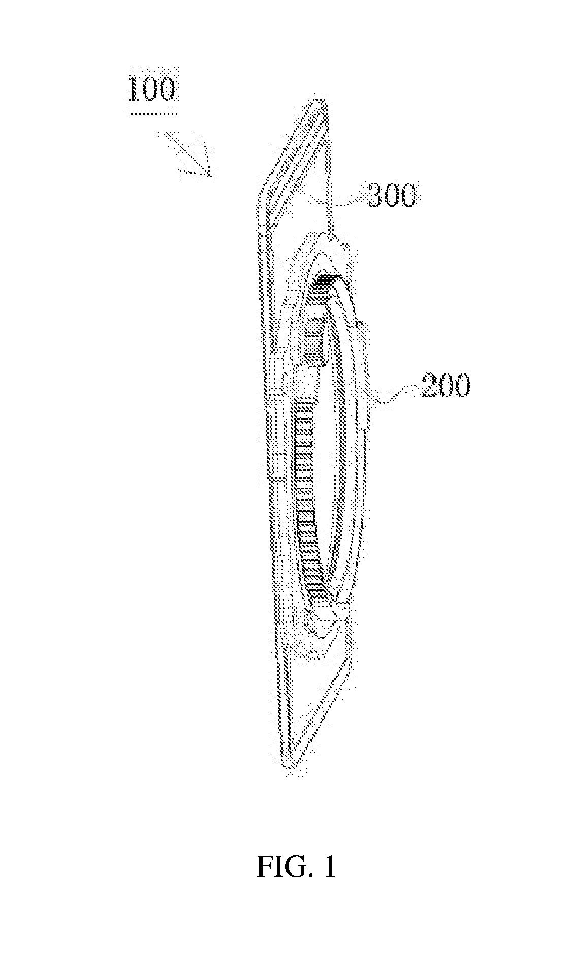
[0036]As shown in FIG. 1, a filter assembly structure 100 of the present invention, comprises a filter holder 200 and a filter 300, wherein the filter 300 is mounted on the filter holder 200 in a way of magnetic attraction, so as to achieves quick mounting and disassembling between the filter 300 and the filter holder 200, and solves the phenomenon of getting stuck when the filter is being mounted on the conventional filter holder. The cancelation of the conventional slot leads to that the thickness of the entire filter holder is greatly reduced and the vignetting will not happen after the filter is mounted, and the photographing effect is improved. When in use, the filter 300 is not easy to slide down due to the quality of the conventional slot of the holder and the filter's own weight, and the mounting is stable and reliable. At the same time, the filter 300 is very flexible and convenient when it is adjusted to slide up and down or to turn left and right.

[0037]In the present embo...


PUM


Abstract

The present invention provides a filter assembly structure, which comprises a filter holder and at least one filter, wherein the at least one filter is mounted on the filter holder in a way of magnetic attraction. In a way of magnetic attraction, the present invention achieves quick mounting and disassembling between the filter and the filter holder, and solves the phenomenon of getting stuck when the filter is being mounted on the conventional filter holder; and the cancelation of the conventional slot leads to that the thickness of the entire filter holder is greatly reduced and the vignetting will not happen after the filter is mounted, and the photographing effect is improved. When in use, the filter is not easy to slide down due to the quality of the conventional slot of the holder and the filter's own weight, and the mounting is stable and reliable. At the same time, the filter is very flexible and convenient when it is adjusted to slide up and down or to turn left and right. Due to the magnetic attraction, no light leakage occurs because of a gap between the filters, and the photographing effect is not affected.

Description

[0001]CROSS REFERENCE TO RELATED APPLICATIONS: Applicant H&Y Digital Company Limited a Hong Kong company principally located in Lai Chi Kok, Kowlon, Hong Kong states that this non-provisional utility patent application claims benefits from and priority to a patent application previously filed with the State Intellectual Property Office of the Peoples Republic of China in Chinese on May 31, 2017, said patent application assigned serial number CN201710401375.2 and incorporated by reference herein in its entirety.TECHNICAL FIELD[0002]The present invention relates to the technical field of photographic equipment and in particular, to a filter assembly structure that facilitates the mounting and adjustment of a filter.STATEMENT REGARDING FEDERALLY SPONSORED RESEARCH OR DEVELOPMENT[0003]No federal funds were used to develop or create the invention disclosed and described in the patent application.BACKGROUND[0004]With the maturation and improvement of photography technology, people's requi...

Claims


Application Information

Patent Timeline
IPC IPC(8): G02B7/00G03B17/56G03B17/12
CPCG02B7/006G03B17/565G03B17/12G03B11/00H04N23/55G02B5/20
Inventor LEUNG, KWOKFAI
Owner H&Y DIGITAL CO LTD
Why Eureka
Try Eureka