Eureka AIR delivers breakthrough ideas for toughest innovation challenges, trusted by R&D personnel around the world.

Electric machine

Active Publication Date: 2018-12-06
DR ING H C F PORSCHE AG
View PDF0 Cites 5 Cited by
  • Summary
  • Abstract
  • Description
  • Claims
  • Application Information

AI Technical Summary

Benefits of technology

The electric machine described in this patent is for an electric vehicle and includes a rotor and stator. A duct system is used to cool the machine, which includes a cooling duct that runs conically within the rotor shaft. The coolant is conveyed in the direction of an increasing duct diameter by the rotation of the rotor shaft. This cooling system allows for a powerful machine and reduces the need for maintenance on the transmission oil. The use of transmission oil as a coolant also allows for additional heating of the transmission, improving efficiency.

Problems solved by technology

Here, the maximum permissible heating has a considerable influence on the performance limit of the electric machine.
It is disadvantageous, however, that the rotor often has to be sealed in a very complicated manner, since the water is as a rule pumped through the rotor shaft under pressure.
In addition, the seal usually causes a very great power loss and frequently also requires a large amount of installation space.
It is a disadvantage of cooling of this type, however; that the transmission oil as a rule experiences pronounced ageing above 120° C. In electric machines and, in particular; in traction motors of electric vehicles, however, the rotor shaft can experience temperatures of 160° C. or more.
The transmission oil can therefore deteriorate in a particularly pronounced and / or rapid manner in the case of cooling of this type.

Method used


Image

  • Electric machine
  • Electric machine

Examples


Embodiment Construction

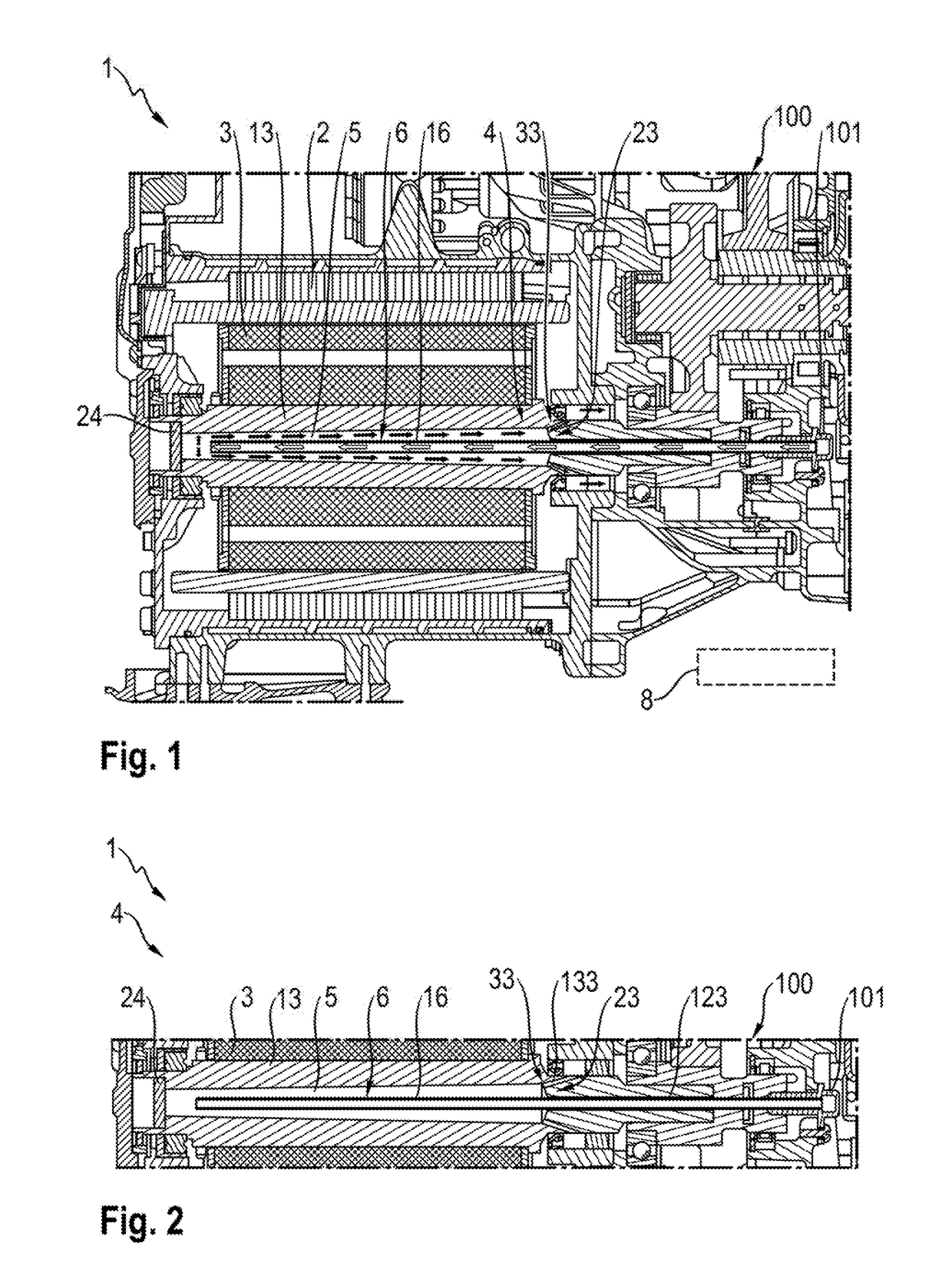
[0052]FIG. 1 shows an electric machine 1 according to aspects of he invention having a transmission device 100 which is attached to it. FIG. 2 shows a detailed view of FIG. 1. The electric machine 1 can be used, for example, in an electric vehicle is according to aspects of the invention for a traction drive.

[0053]Here, the electric machine 1 comprises a stator 2 and a rotor 3 which is received rotatably in the stator 2. Here, the rotor 3 comprises a rotatably mounted rotor shaft 13. Here, an end section of the rotor shaft 13 is mounted in a housing of the machine 1.

[0054]Here, another end section of the rotor shaft 13 protrudes out of the housing of the machine 1 and provides the output-side shaft end. Here, said end of the rotor shaft 13 is connected to the transmission device 100, with the result that the transmission device 100 can be driven by way of the machine 1.

[0055]Here, in order to discharge heat, a duct system 4 is provided which can be flowed through by a liquid coolant...


PUM


Abstract

An electric machine, in particular for an electric vehicle. The machine includes a rotor which can be rotated with respect to a stator and has at least one rotor shaft. The machine includes a duct system for cooling the machine, through which duct system a coolant can flow. The duct system runs at least in sections within the rotor shaft. Here, the duct system includes a cooling duct. The cooling duct is configured so as to run conically at least in sections in the longitudinal direction of the rotor shaft, such that the coolant can be conveyed in the direction of an increasing duct diameter by way of a rotational movement of the rotor shaft.

Description

CROSS-REFERENCE TO RELATED APPLICATION[0001]This application claims priority to German Patent Application No. DE 10 2017 12 348.2, filed Jun. 6, 2017, which is incorporated by reference herein in its entirety.FIELD OF THE INVENTION[0002]The present invention relates to an electric machine which is provided, in particular, for an electric vehicle. The machine comprises at least one rotor which can be rotated with respect to at least one stator and has at least one rotor shaft. The electric machine has at least one duct system for cooling the machine, through which duct system a coolant can flow and which duct system runs at least in sections within the rotor shaft.BACKGROUND OF THE INVENTION[0003]The electric machines which are configured as traction motors in electric vehicles are as a rule heated to a very pronounced extent during operation. Here, the maximum permissible heating has a considerable influence on the performance limit of the electric machine.[0004]Liquid cooling is th...

Claims


Application Information

Patent Timeline
IPC IPC(8): H02K9/193H02K1/32
CPCH02K9/193H02K1/32H02K9/197H02K7/116Y02T10/64
Inventor KNOBLAUCH, DANIELWACHTER, SEBASTIAN
Owner DR ING H C F PORSCHE AG
Why Eureka
Eureka Blog
Learn More