Dc-dc converting circuit and multi-phase power controller thereof

Active Publication Date: 2018-12-06
UPI SEMICON CORP
View PDF0 Cites 3 Cited by
  • Summary
  • Abstract
  • Description
  • Claims
  • Application Information

AI Technical Summary

Benefits of technology

The new DC-DC converting circuit in this patent can better control the conversion of input to output voltage. It uses a multi-phase power controller to adjust both the duty cycle of the PWM signal and the switching frequency to achieve current balance and linear voltage regulation, reducing switching loss and improving overall performance. This can lead to better performance and reduced loss in the system.

Problems solved by technology

However, in practical applications, when each phase resonant power converting circuit in a conventional multi-phase resonant power converting circuit has a different parasitic inductance capacitance, even at the same frequency, each phase resonant power converting circuit will have different voltage gains, resulting in a reduction of the overall system performance, and due to the lack of current balance control mechanism of the conventional multi-phase resonant power converting circuit, it is difficult to effectively improve the current efficiency in parallel connection.

Method used


Image

  • Dc-dc converting circuit and multi-phase power controller thereof
  • Dc-dc converting circuit and multi-phase power controller thereof
  • Dc-dc converting circuit and multi-phase power controller thereof

Examples


Embodiment Construction

[0026]Exemplary embodiments of the present invention are referenced in detail now, and examples of the exemplary embodiments are illustrated in the drawings. Further, the same or similar reference numerals of the elements / components in the drawings and the detailed description of the invention are used on behalf of the same or similar parts.

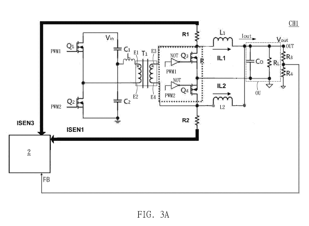
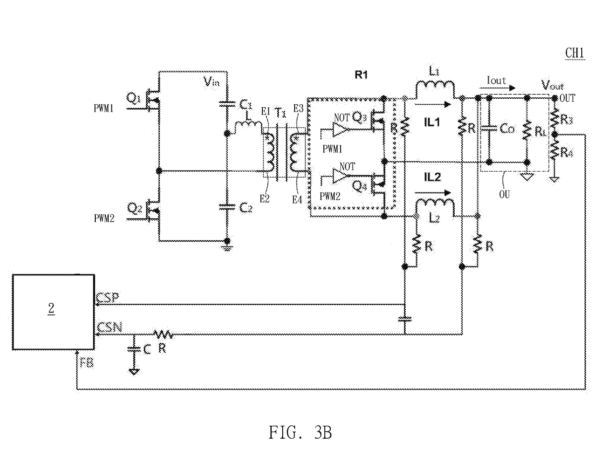
[0027]A preferred embodiment of the invention is a multi-phase power controller. In this embodiment, the multi-phase power controller can be used in a power converting apparatus (e.g., a DC-DC power converter). The multi-phase power controller can be coupled to resonant power converting circuits respectively and provide the pulse-width modulation signal to each resonant power converting circuit respectively to control the operation of each resonant power converting circuit to provide a function of converting the input voltage (Vin) into the output voltage (Vout).

[0028]For example, the power converting apparatus can convert an input voltage (Vin) ...


PUM


Abstract

A multi-phase power controller coupled to resonant power converting circuits providing an output voltage is disclosed. The multi-phase power controller includes a current sensing unit, a frequency adjusting circuit and a duty cycle adjusting circuit. The current sensing unit, coupled to a first resonant power converting circuit, provides a first sensing current. The frequency adjusting circuit includes an error amplifier and a first ramp signal generation circuit. The error amplifier provides an error signal according to the output voltage and a reference voltage. The first ramp signal generation circuit provides a first ramp signal according to the error signal. The duty cycle adjusting circuit provides a first PWM signal to the first resonant power converting circuit according to a default voltage and the first ramp signal. The change of the duty cycle of the first PWM signal is related to the first sensing current, the default voltage and the first ramp signal.

Description

BACKGROUND OF THE INVENTION1. Field of the Invention[0001]The invention relates to resonant power converting circuits; in particular, to a DC-DC converting circuit and a multi-phase power controller used for controlling the resonant power converting circuits.2. Description of the Prior Art[0002]In general, in the field of network equipment or automotive electronics, power converters are usually used to convert high voltages to low voltages. For example, FIG. 1 illustrates a schematic diagram of a conventional multi-phase resonant power converting circuit. When the output load Rload of the conventional multi-phase resonant power converting circuit fluctuates, its multi-phase power controller usually outputs a pulse width modulation signal with a fixed duty cycle to the resonant power converting circuit and changes switching frequency according to a voltage feedback signal related to the output voltage Vo to achieve the linear voltage regulation function.[0003]However, in practical ap...

Claims


Application Information

Patent Timeline
IPC IPC(8): H02M3/158H03K7/08H03K5/00H03K4/48
CPCH02M3/1584H03K7/08H03K5/00006H03K4/48H02M2001/0009H02M3/33507H02M3/33592H02M1/0054H02M3/285Y02B70/10H02M1/0009
Inventor LIU, HSIEN-CHENGLIU, ZHAO-WAICHEN, LIANG-YI
Owner UPI SEMICON CORP
Why Eureka
Try Eureka