Switch device for in-vehicle power supply, and in-vehicle power supply device

a technology of in-vehicle power supply and switch device, which is applied in the direction of safety/protection circuit, emergency protective arrangement for limiting excess voltage/current, transportation and packaging, etc., can solve the problems of increased power consumption and longer period of time, and achieve the effect of lowering the ground fault curren

Inactive Publication Date: 2018-12-13
AUTONETWORKS TECH LTD +2
View PDF3 Cites 23 Cited by
  • Summary
  • Abstract
  • Description
  • Claims
  • Application Information

AI Technical Summary

Benefits of technology

[0006]However, in JP 2015-83404A, the sub battery is charged via multiple switches that are connected in series. When the sub battery is charged via multiple switches in this way, the sub battery is charged via a high resistance value. Accordingly, power consumption increases, or a longer period of time is required for charging, for example. In other words, it is hard to say that the configuration in JP 2015-83404A is suited to the charging of the sub battery.
[0015]According to the second and third aspects of the in-vehicle power supply switch device, it is possible to lower the ground fault current.
[0016]According to the fourth aspect of the in-vehicle power supply switch device, it is possible to retain the amount of power stored in the lead battery.
[0017]According to the fifth aspect of the in-vehicle power supply switch device, it is possible to handle a ground fault with a small number of times that switches are switched.

Problems solved by technology

Accordingly, power consumption increases, or a longer period of time is required for charging, for example.

Method used


Image

  • Switch device for in-vehicle power supply, and in-vehicle power supply device
  • Switch device for in-vehicle power supply, and in-vehicle power supply device
  • Switch device for in-vehicle power supply, and in-vehicle power supply device

Examples


Embodiment Construction

[0037]Configuration

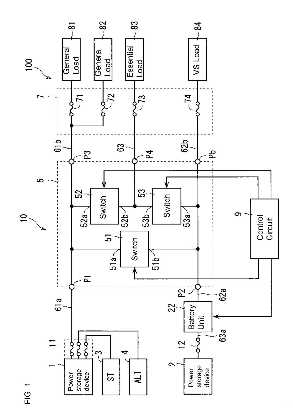
[0038]FIG. 1 is a diagram schematically showing an example of the configuration of an in-vehicle power supply system 100. The in-vehicle power supply system 100 is for installation in a vehicle. This in-vehicle power supply system 100 includes at least an in-vehicle power supply device 10 and loads 81 to 84. As illustrated in FIG. 1, the in-vehicle power supply system 100 may further include a battery unit 22, a starter 3, a generator 4, a fuse box 7, a group of fuses 11, and a fuse 12. The group of fuses 11 is realized by a battery fuse terminal (BTF), for example.

[0039]The in-vehicle power supply device 10 includes power storage devices 1 and 2 and a switch device 5. The switch device 5 is an in-vehicle power supply switch device, with the power storage devices 1 and 2 provided at the input side thereof, and the loads 81 to 84 provided at the output side thereof. This switch device 5 is a device that switches the electrical connection relationship between power ...


PUM


Abstract

An in-vehicle power supply switch device that is suited to charging is provided. A first switch is connected between a first load and a first power storage device. A second switch is connected between the first load and a second power storage device. A third switch is connected in parallel to a set of the first switch and the second switch, and has a smaller resistance value than both the resistance value of the first switch and the resistance value of the second switch.

Description

CROSS-REFERENCE TO RELATED APPLICATIONS[0001]This application is the U.S. national stage of PCT / JP2017 / 003305 filed Jan. 31, 2017, which claims priority of Japanese Patent Application No. 2016-027719 filed on Feb. 17, 2016, which is incorporated herein by reference in its entirety.FIELD OF THE INVENTION[0002]This description relates to an in-vehicle power supply switch device and an in-vehicle power supply device.BACKGROUND OF THE INVENTION[0003]An in-vehicle power supply device is disclosed in JP 2015-83404A. This in-vehicle power supply device includes a main battery, a sub battery, first to third switches, and a group of auxiliary devices. The first switch is connected between the main battery and the group of auxiliary devices, and the second switch and third switch are connected to each other in series between the sub battery and the group of auxiliary devices.[0004]In this in-vehicle power supply device, when an abnormality occurs on the main battery side, the main battery can...

Claims


Application Information

Patent Timeline
Patent Type & Authority Applications(United States)
IPC IPC(8): B60R16/033H02J7/00H02H3/16
CPCB60R16/033H02J7/0031H02J7/0054H02H3/16H02J2007/0059H02H7/18H02J7/0034H02J7/1423H02H3/021H02H7/1203H02H7/1225H02H7/268H02H7/28H02H9/00H02H9/001H02J2207/20H02J2310/46H02H3/05H02H3/087H02J7/342
Inventor SATO, SHINICHIRO
Owner AUTONETWORKS TECH LTD
Why Eureka
Try Eureka