
Blended wing body aircraft

a blended and wing body technology, applied in the field of aircraft profiles, can solve the problems of impeded aerodynamic efficiency and design cannot be simply scaled down for smaller aircraft, and achieve the effect of limiting aerodynamic efficiency and large wetted area

Active Publication Date: 2018-12-20
BOMBARDIER CORP
View PDF0 Cites 2 Cited by
  • Summary
  • Abstract
  • Description
  • Claims
  • Application Information

AI Technical Summary

Benefits of technology

The patent describes a blended wing body aircraft that has a unique design. The aircraft has a center body and two wings that extend from the center body. The design has specific ratios for the thickness and chord length of each section of the aircraft. The ratios are set forth in a table. The aircraft also has a normalized half-span length, which is the distance from the centerline of the center body to the tip of the wings. The normalized half-span length has a specific range for each profile section of the aircraft. The design of the aircraft is optimized to achieve maximum efficiency and performance. The aircraft may also have a maximum chord length, a maximum width, and a cabin aspect ratio. The design of the aircraft also includes a reference line for reference during construction. Overall, the patent describes a blended wing body aircraft with a unique design that has specific ratios for the thickness and chord length of each section, as well as a maximum chord length, width, and cabin aspect ratio.

Problems solved by technology

Such designs cannot simply be scaled down for smaller aircraft, as the resulting height would not be suitable to accommodate passengers.
Typical blended wing body aircraft have a relatively large wetted area, which may impede aerodynamic efficiency.

Method used


Image

  • Blended wing body aircraft
  • Blended wing body aircraft
  • Blended wing body aircraft

Examples


Embodiment Construction

[0048]In the present specification, including claims, it is understood that a range of values formulated as “from X to Y” is inclusive, i.e. includes the values X and Y.

[0049]Blended wing body designs are sometimes also referred to as “hybrid wing body” designs. In the present specification, including claims, it is understood that the term “blended wing body” encompasses designs which are sometime referred to as “hybrid wing body” designs.

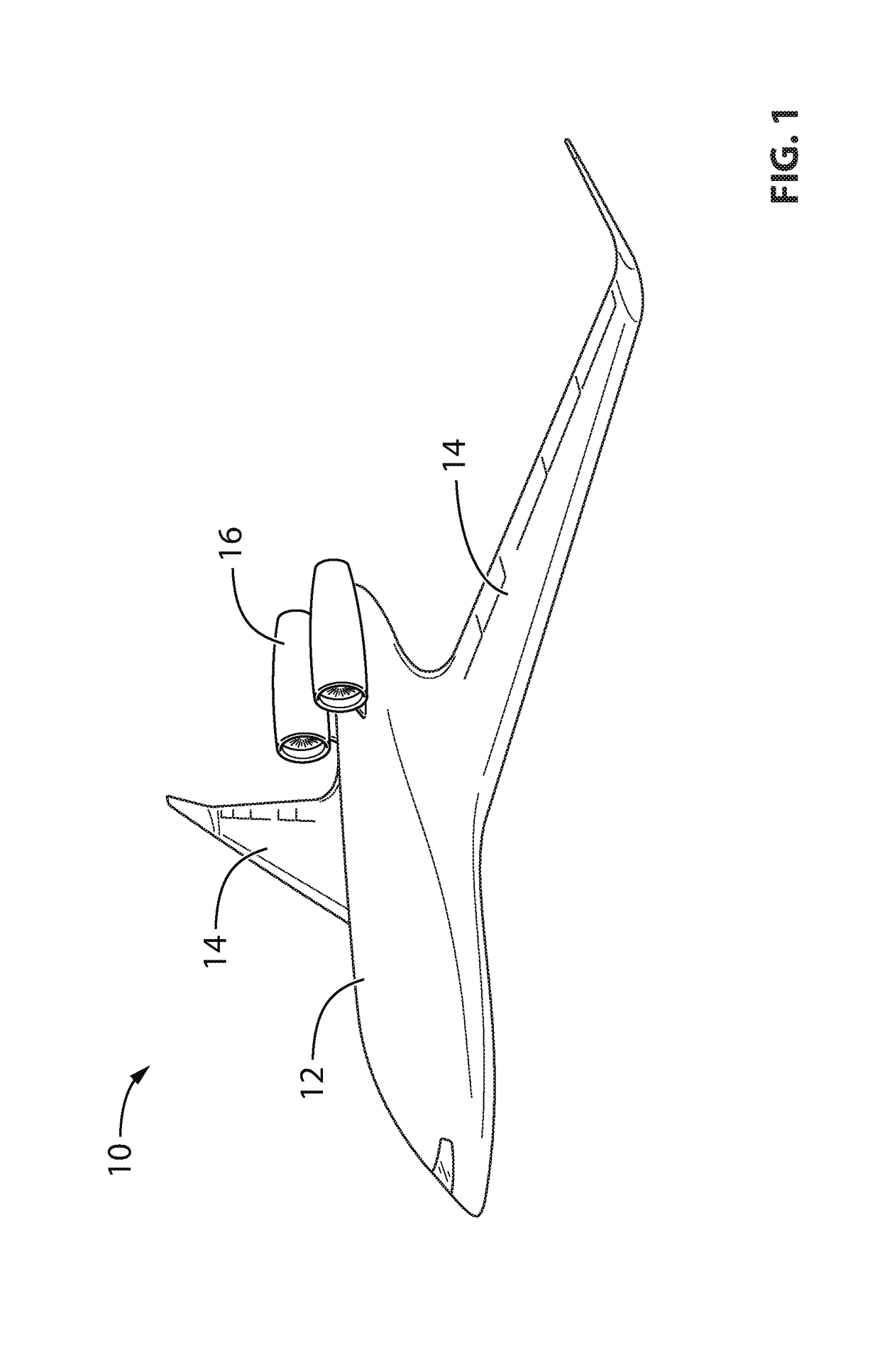
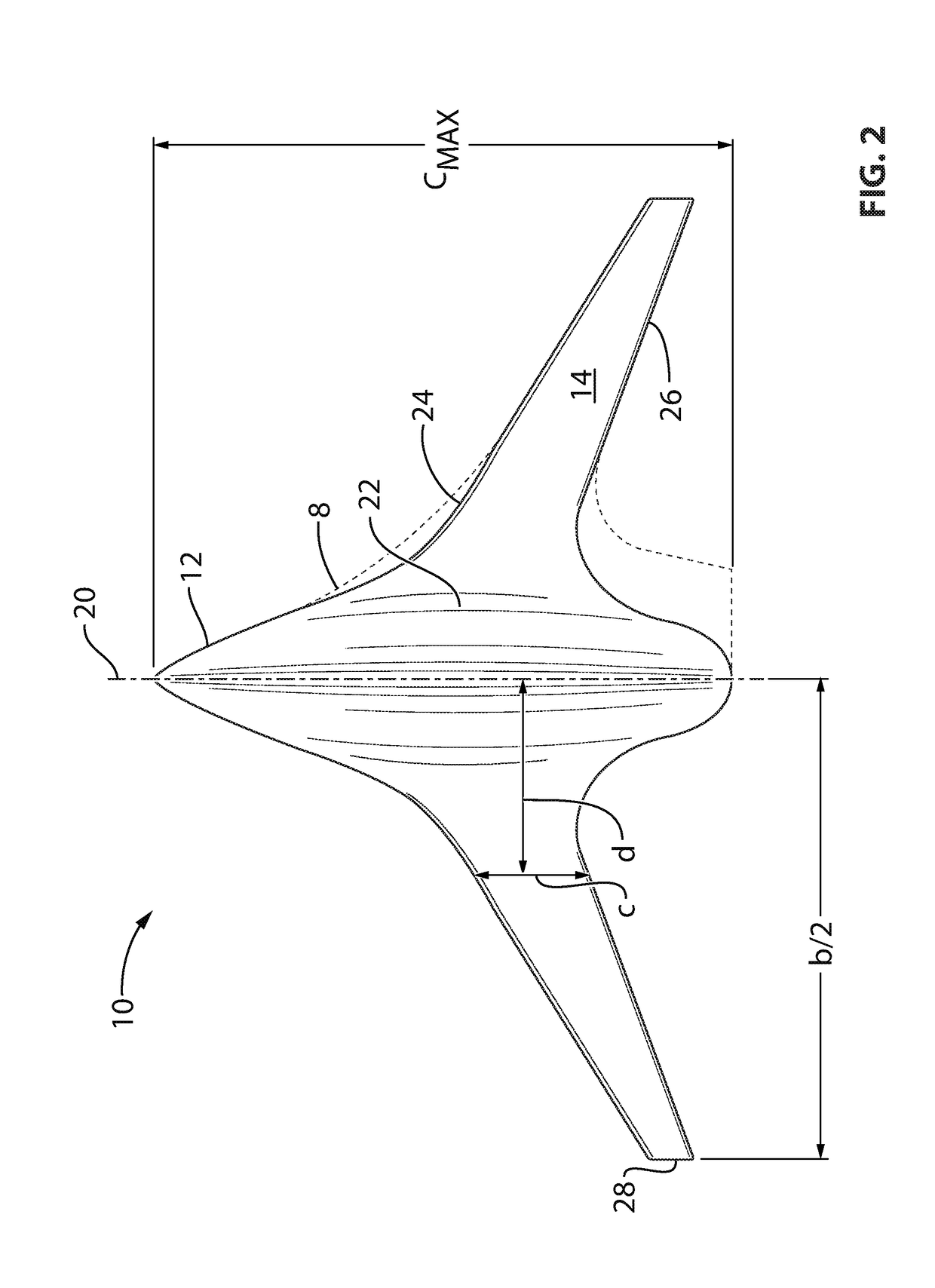
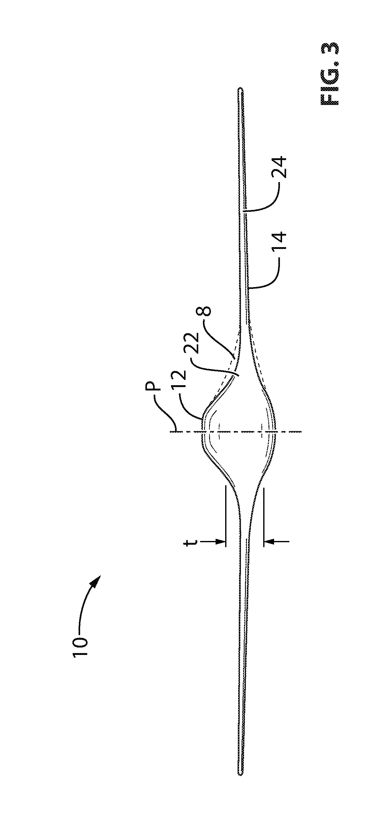
[0050]Referring to the drawings and more particularly to FIG. 1, a blended wing body aircraft is shown at 10. The aircraft 10 has a center body 12 having a fore end at which a cockpit is located, and an opposed aft end. The center body 12 is airfoil-shaped such as to be able to generate lift. In the embodiment shown, the aircraft 10 is tailless; alternately, a tail structure may be provided at the aft end of the center body 12 and / or a canard may be provided at the fore end of the center body 12. Wings 14 project laterally from opposite sides of th...


PUM


Abstract

A blended wing body aircraft wherein at least each profile section corresponding to the normalized half-span values from 0 to 0.2 has a thickness ratio having a nominal value within the range set forth in Table 1. Also, a blended wing body aircraft wherein at least each profile section corresponding to the normalized half-span values from 0.15 to 0.3 has a normalized chord having a nominal value within the range set forth in Table 1, and wherein a ratio between a maximum thickness of the center body and the chord length along the centerline has a nominal value of at least 16%. Also, a blended wing body aircraft wherein a region of the aircraft defined by normalized half-span values from 0.1 to 0.2 has a normalized chord having a dimensionless rate of change from −3.5 to −5.1, and a thickness ratio having a rate of change from −0.27 to −0.72.

Description

CROSS-REFERENCE TO RELATED APPLICATIONS[0001]This application claims priority from U.S. provisional application No. 62 / 265,000 filed Dec. 9, 2015 and U.S. provisional application No. 62 / 291,273 filed Feb. 4, 2016, the entire contents of both of which are incorporated by reference herein.TECHNICAL FIELD[0002]The application relates generally to aircraft profiles and, more particularly, to the profile of a blended wing body aircraft.BACKGROUND OF THE ART[0003]A number of blended wing body designs are known, but such are typically designed for relatively large aircraft, for example seating 200 people or more. Such designs cannot simply be scaled down for smaller aircraft, as the resulting height would not be suitable to accommodate passengers.[0004]Typical blended wing body aircraft have a relatively large wetted area, which may impede aerodynamic efficiency.SUMMARY[0005]In one aspect, there is provided a blended wing body aircraft comprising: an airfoil shaped center body; and a pair ...

Claims


Application Information

Patent Timeline
Patent Type & Authority Applications(United States)
IPC IPC(8): B64C39/10B64C1/00B64C3/14
CPCB64C39/10B64C1/0009B64C3/14B64C2039/105Y02T50/10
Inventor BANERJEE, SIDDHARTHOGALIN, ALEXANDRECHITTICK, IAN
Owner BOMBARDIER CORP
Learn More