Integrated photovoltaic module mounting system for use with tufted geosynthetics

a photovoltaic module and mounting system technology, applied in the field of non-integrated mounting systems for photovoltaic modules, can solve the problems of limiting the number of photovoltaic modules that can be installed, the installation of rigid racking systems has not been integrated onto the photovoltaic module, and the drawback of such installations, so as to reduce the maintenance of the surrounding surface, generate more solar power per unit area, and reduce the cost

Active Publication Date: 2018-12-20
WATERSHED SOLAR LLC
View PDF3 Cites 10 Cited by
  • Summary
  • Abstract
  • Description
  • Claims
  • Application Information

AI Technical Summary

Benefits of technology

[0015]The integrated mounting system of this invention allows for easy installation supported by a tufted geosynthetic on a surface. This combination of the integrated mounting system and tufted geosynthetic results in a lower cost, lower maintenance of the surrounding surface, adaptable for variety of grades from flat to sloping ground and generates more solar power per unit area.

Problems solved by technology

These rigid racking systems have not been integrated onto the photovoltaic module.
However, the spacing limits the number of photovoltaic modules that can be installed in an area because the angling causes shadows.
While use of solar as a renewable alternative energy source has “clean energy” favorabilities, there are drawback to such installations.
Solar energy generation sites typically require large tracts of land.
Other sites are significantly remote from tie-in connections to the power transmission and distribution grid of power generating and supply companies.
These remote sites require capital expenditures to install and maintain transmission lines to the electrical grid and such transmission lines occupy additional land.

Method used


Image

  • Integrated photovoltaic module mounting system for use with tufted geosynthetics
  • Integrated photovoltaic module mounting system for use with tufted geosynthetics
  • Integrated photovoltaic module mounting system for use with tufted geosynthetics

Examples


Embodiment Construction

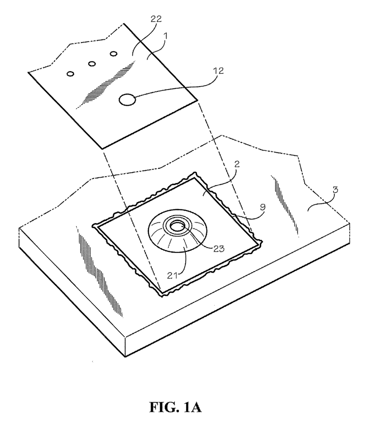
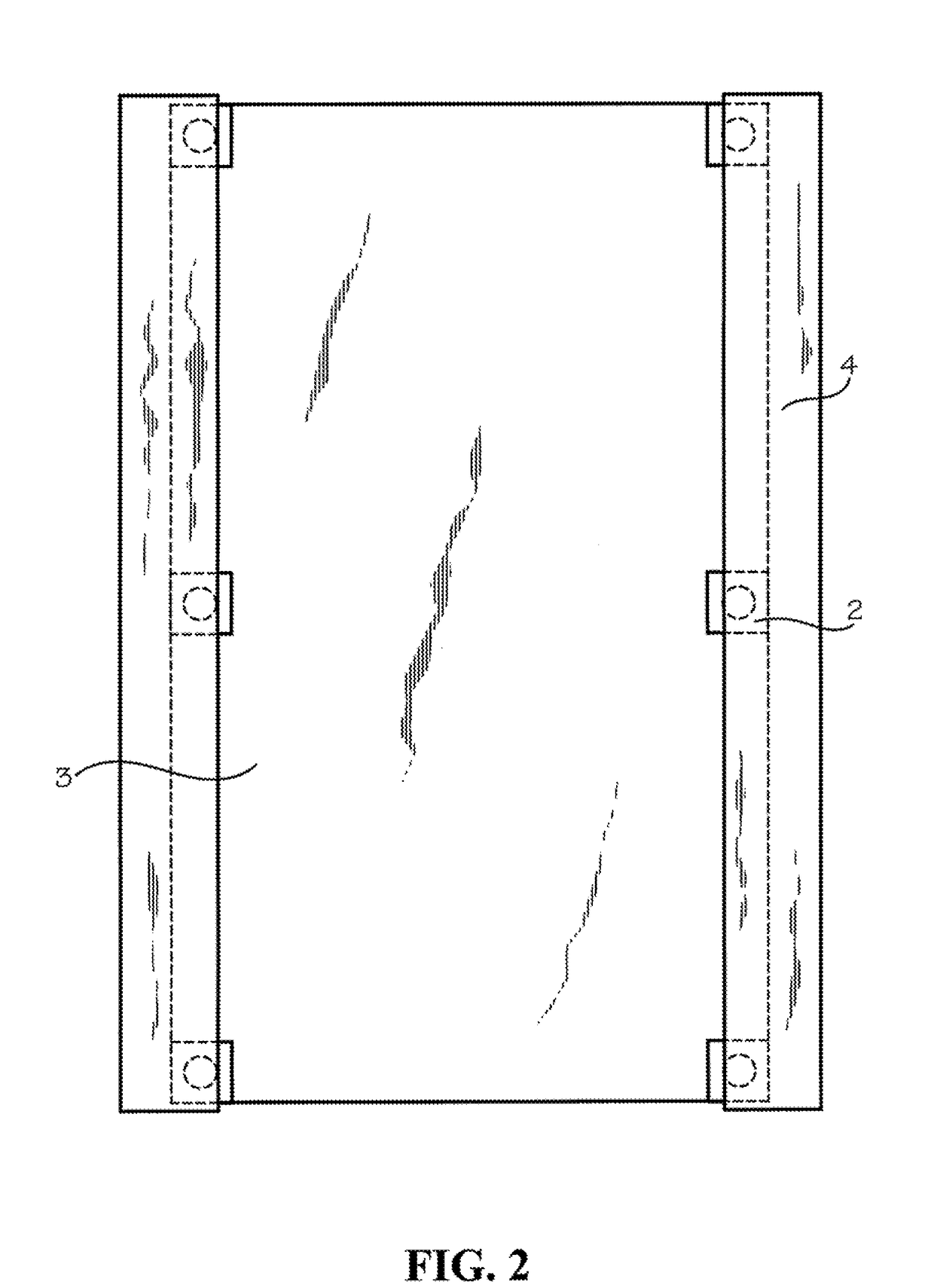
[0052]The present invention provides an integrated photovoltaic module mounting system for use with a tufted geosynthetic system on a surface without a racking structure and without ballast for support.

[0053]The essential components of this invention are a tufted geosynthetic system and one or more integrated photovoltaic module mounting systems.

[0054]Cover System

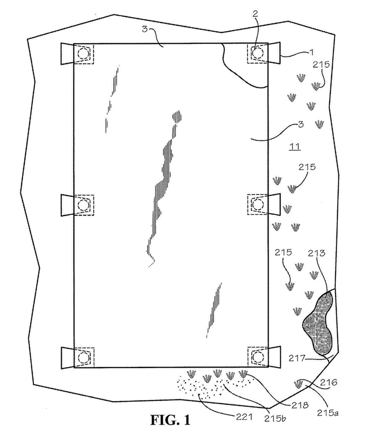
[0055]Examples of tufted geosynthetic systems useful in the integrated photovoltaic module mounting system of this invention are the covers marketed by Watershed Geosynthetics LLC under the registered trademarks ClosureTurf and VersaCap. These covers 11 comprise a composite of at least one geotextile 213 which is tufted with a plurality of spaced-apart tufts 215 with one or more synthetic yarns (i.e., a tufted geosynthetic) to simulate grass blades in a synthetic grass, and an impermeable geomembrane 217 comprised of a polymeric material.

[0056]The synthetic grass blades of the system may contain an infill material and / or a ...


PUM


Abstract

A mounting system 10 for a solar panel 11 includes a base plate 14 having a mounting channel 16 defined by an elongated base member 17, two oppositely disposed elongated channel walls 18 having clamping tangs 19, and a support wall 20. The mounting system also includes an I-beam 24 having a lower member 25, an upper member 26 and a spanning member 27. A C-shaped bracket 30 is slidably coupled to the upper member and has a mounting post with a staggered clamp 36 having a contact ledge 37. A nut 38 is threadably coupled to the mounting post 32 to force the contact ledge downwardly against the peripheral margin of the solar panel, thus locking the position of the solar panel. The mounting system includes a weld harness or weld harness strip 39 and anti-creep strips 44 which are coupled to the base member.

Description

CROSS REFERENCE TO RELATED APPLICATIONS[0001]This application claims the benefit of U.S. Provisional Patent Application Ser. No. 62 / 616,705 filed Jan. 12, 2018 and entitled Integrated Photovoltaic Module Mounting System For Use With Tufted Geosynthetics. This application also claims the benefit of U.S. Provisional Patent Application Ser. No. 62 / 522,402 filed Jun. 20, 2017 and entitled Integrated Photovoltaic Module Mounting System For Use With Tufted Geosynthetics.STATEMENT REGARDING FEDERALLY SPONSORED RESEARCH OR DEVELOPMENT[0002]Not applicable.TECHNICAL FIELD[0003]This invention relates to an integrated mounting system for photovoltaic modules for use in solar energy collection. In a more specific aspect, this invention relates to a non-ballasted and non-ground penetrating integrated photovoltaic mounting system for use with, and supported by, tufted geosynthetics.[0004]In this application, the following terms will be understood to have the indicated definitions:[0005]“photovolta...

Claims


Application Information

Patent Timeline
Patent Type & Authority Applications(United States)
IPC IPC(8): H02S30/10F24S25/20H01L31/0475F24S25/634H02S20/20
CPCH02S30/10F24S25/20H01L31/0475F24S25/634H02S20/20F24S2025/6003F24S2025/6005F24S25/636F24S25/61F24S25/632F24S25/13F24S25/33H02S20/10Y02E10/52H02S20/23Y02B10/10Y02E10/50H02S20/25H02S40/22H02S40/425
Inventor AYERS, MICHAEL R.EHMAN, S. KYLEREEF, NETAZEHAVI, SHARONE
Owner WATERSHED SOLAR LLC
Why Eureka
Try Eureka