Damper for a bicycle component

a technology for bicycle components and derailleur bodies, which is applied in the direction of bicycle brakes, chain/belt transmissions, vehicle components, etc., can solve the problems of chain tensioners that cannot be rotated in the chain slackening direction, chain slapping against the frame of the bicycle, and the chain is slack

Active Publication Date: 2018-12-27
SRAM CORPORATION
View PDF39 Cites 14 Cited by
  • Summary
  • Abstract
  • Description
  • Claims
  • Application Information

AI Technical Summary

Benefits of technology

[0009]In one example, the friction member is a torsion spring including a tab at a first end of the friction member. The tab of the torsion spring is positioned within a corresponding recess within the movable member. The torsion spring is configured to apply a radial spring force to the pivot member as the chain guide assembly rotates in the second rotational direction relative to the movable member from a first rotational position to a second rotational position. The radial spring force is greater and an inner diameter of the torsion spring is smaller when the chain guide assembly is in the second rotational position compared to when the chain guide assembly is in the first rotational position.

Problems solved by technology

However, when a bicycle travels over rough terrain, the forces transmitted to the rear derailleur can cause the chain tensioner to undesirably rotate in the chain slackening direction against the biasing force applied to the chain tensioner.
This creates a slack condition in the chain.
A slack chain can lead to the chain slapping against the frame of the bicycle.
A slack chain can also lead to the chain falling off the sprockets or cogs.
These roller clutch based friction type damping systems are relatively heavy, which runs counter to a common performance goal of reducing bicycle weight.
Further, this type of friction damping system may be rather complicated in construction, requiring multiple parts and numerous manufacturing steps.
One result of the complicated nature of roller clutch based friction type damping systems is that the parts are relatively expensive, which increases the cost of the rear derailleurs.

Method used


Image

  • Damper for a bicycle component
  • Damper for a bicycle component
  • Damper for a bicycle component

Examples


Embodiment Construction

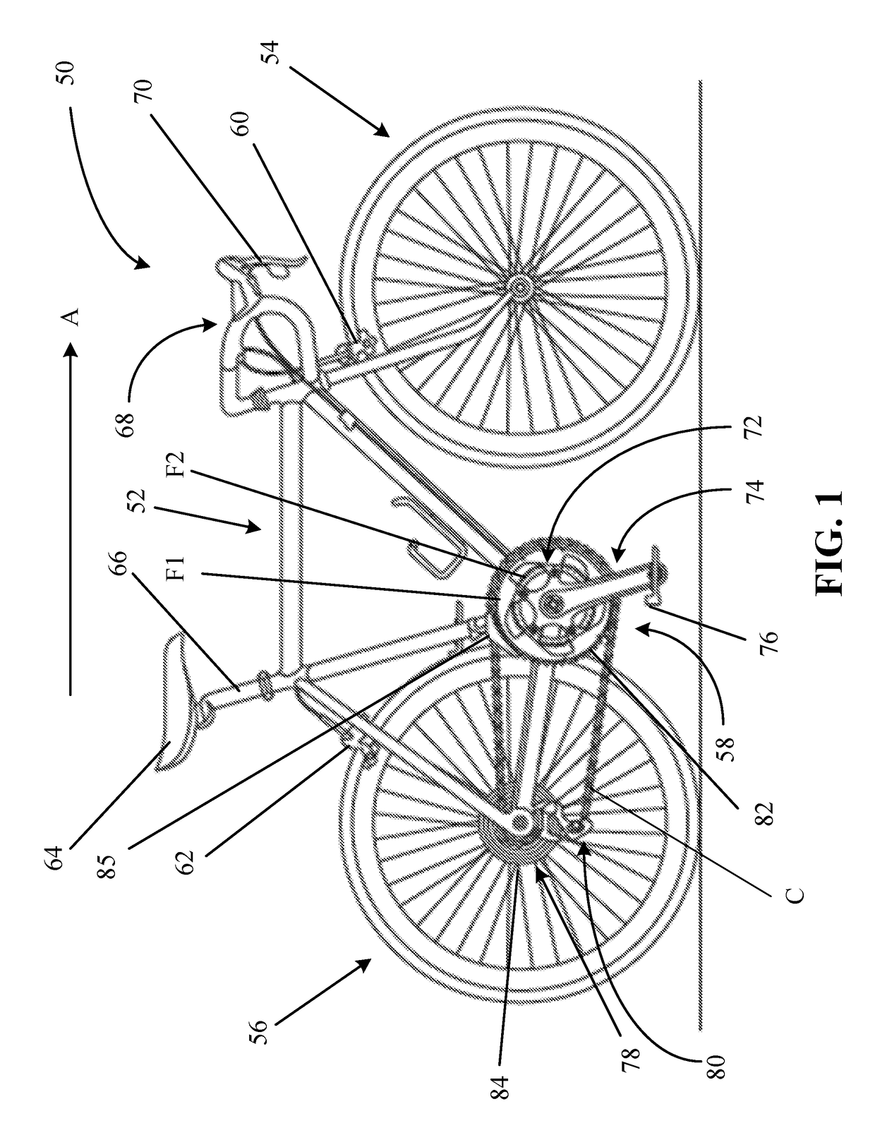
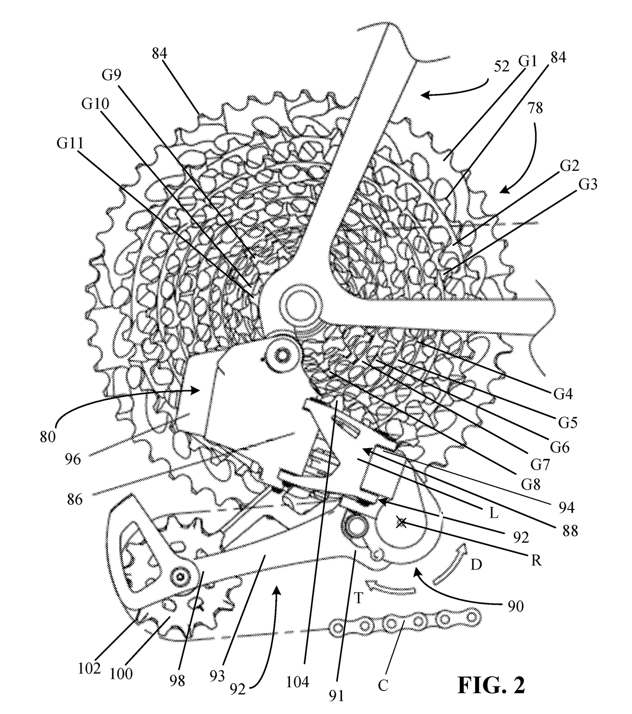
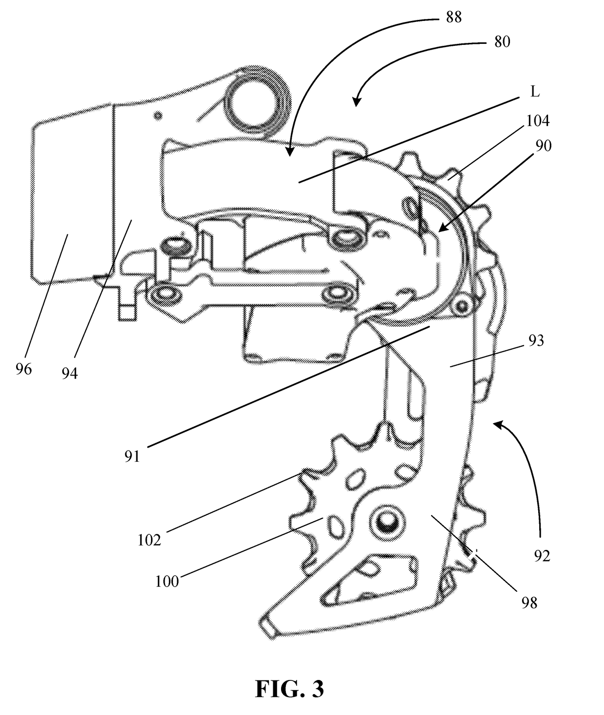
[0044]The present disclosure provides examples of friction dampers and bicycle rear derailleurs that solve or improve upon one or more of the above-noted and / or other disadvantages with prior known dampers and derailleurs. The disclosed friction dampers eliminate the need to include roller clutches in the damper. The friction damper restricts derailleur chain tensioner movement in a forward chain tensioner rotational direction and helps control a chain oscillatory amplitude (e.g., a vertical chain amplitude) of a lower half of the chain when the bicycle is subject to ground input (e.g., vertical ground input). A significant advantage of the disclosed friction dampers is that damping forces are higher when the derailleur chain tensioner is rotated in the forward chain tensioner rotational direction compared to the backward chain tensioner rotational direction. The higher damping forces in the forward chain tensioner rotational direction help limit the chain amplitude, while the lower...


PUM


Abstract

A bicycle rear derailleur includes a movable member and a chain guide assembly rotatably connected to the movable member. The bicycle rear derailleur also includes a pivot member non-rotatably coupled to the chain guide assembly and having an outer annular surface, a biasing device configured to bias the chain guide assembly in a first rotational direction relative to the movable member, and a damper device disposed between the chain guide assembly and the movable member. The damper device is operable to apply a damping force to the chain guide assembly when the chain guide assembly rotates in a second rotational direction relative to the movable member. The damper device includes a friction device that is radially inner relative to the biasing device. The friction device includes a friction member having at least one friction surface biased against and in frictional engagement with the pivot member.

Description

BACKGROUND1. Field of the Disclosure[0001]The present disclosure is generally directed to a bicycle chain tensioner, and more particularly, to a damper for a bicycle rear derailleur.2. Description of Related Art[0002]Bicycle rear derailleurs are well known in the art as a part of a drivetrain of a bicycle. The typical drivetrain also includes a crank assembly that is coupled to one or more sprockets. The crank assembly is operable to drive a chain that is routed or wrapped around one of the sprockets. The chain is also routed to the rear wheel of the bicycle.[0003]Rear derailleurs are provided as a part of the drivetrain to perform two basic functions. The primary function of the rear derailleur is to selectively shift a bicycle chain of the drivetrain among a series of different diameter cogs that are attached to the rear wheel. Shifting of the bicycle chain from one cog to another at the rear wheel is done in order to change the gear ratio of the drivetrain. The secondary function...

Claims


Application Information

Patent Timeline
Patent Type & Authority Applications(United States)
IPC IPC(8): B62M9/126B62M9/16B62M9/128B62K19/18
CPCB62M9/126B62M9/16B62L3/00B62K19/18B62M9/128B62M9/1248B62M9/1244
Inventor CHANG, JIH-HUNG
Owner SRAM CORPORATION
Why Eureka
Try Eureka