Single cavity diverter valve

a diverter valve and single cavity technology, applied in the direction of valve housings, valve operating means/releasing devices, mechanical devices, etc., can solve the problems of shortening the life of the spring and the diverter valve, compromising the operation of the spring, etc., to improve the diverter, simplify the construction, and the effect of reducing the risk of rust and corrosion

Active Publication Date: 2019-01-03
XIAMEN LOTA INT CO LTD
View PDF11 Cites 3 Cited by
  • Summary
  • Abstract
  • Description
  • Claims
  • Application Information

AI Technical Summary

Benefits of technology

[0005]It is an object of the invention to provide an improved diverter valve. The valve of the invention has a simplified construction, and has parts that are less susceptible to rust and corrosion. The diverter valve of the invention is therefore likely to provide its user with a relatively longer service life
[0008]Components are secured to the valve core, and move with the valve core upon its rotation by means of the swivel knob. These components alternatively block fluid from entering, or permit fluid to enter, one or more of the water inlet, first water outlet, and second water outlet. In this way, rotation of the swivel knob and the resultant swiveling of the valve core serve to control the direction of water flow through the diverter valve.
[0014]The invention includes a baffle that is positioned within the valve cavity, and which decreases the force of the water into or out of that cavity.
[0016]A spring positioner is housed within the swivel knob. The spring positioner helps facilitate movement of the swivel knob into any of several different positions, so that access to the water inlet or first and second water outlets can be enabled or stopped.
[0022]This construction also avoids the corrosion problems inherent in water diverter valves that rely upon springs that reside within waterways. This feature extends the service life of the water diverter valve of the invention.

Problems solved by technology

The accumulated minerals can compromise the operation of the spring, and substantially shorten the life of the spring and the diverter valve.

Method used


Image

  • Single cavity diverter valve
  • Single cavity diverter valve
  • Single cavity diverter valve

Examples


Embodiment Construction

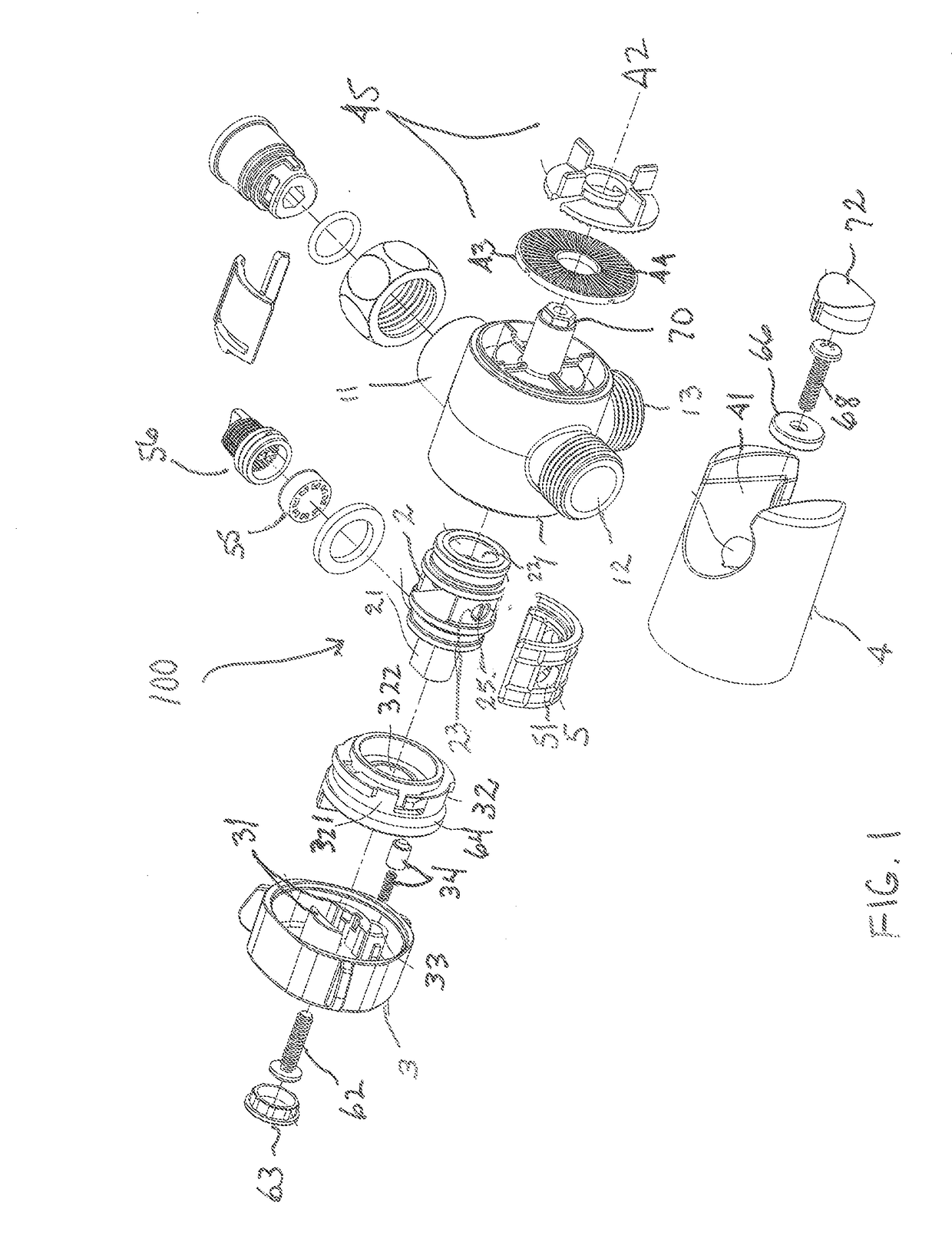
[0032]One embodiment of the diverter valve 100 of the invention is shown in FIGS. 1-8.

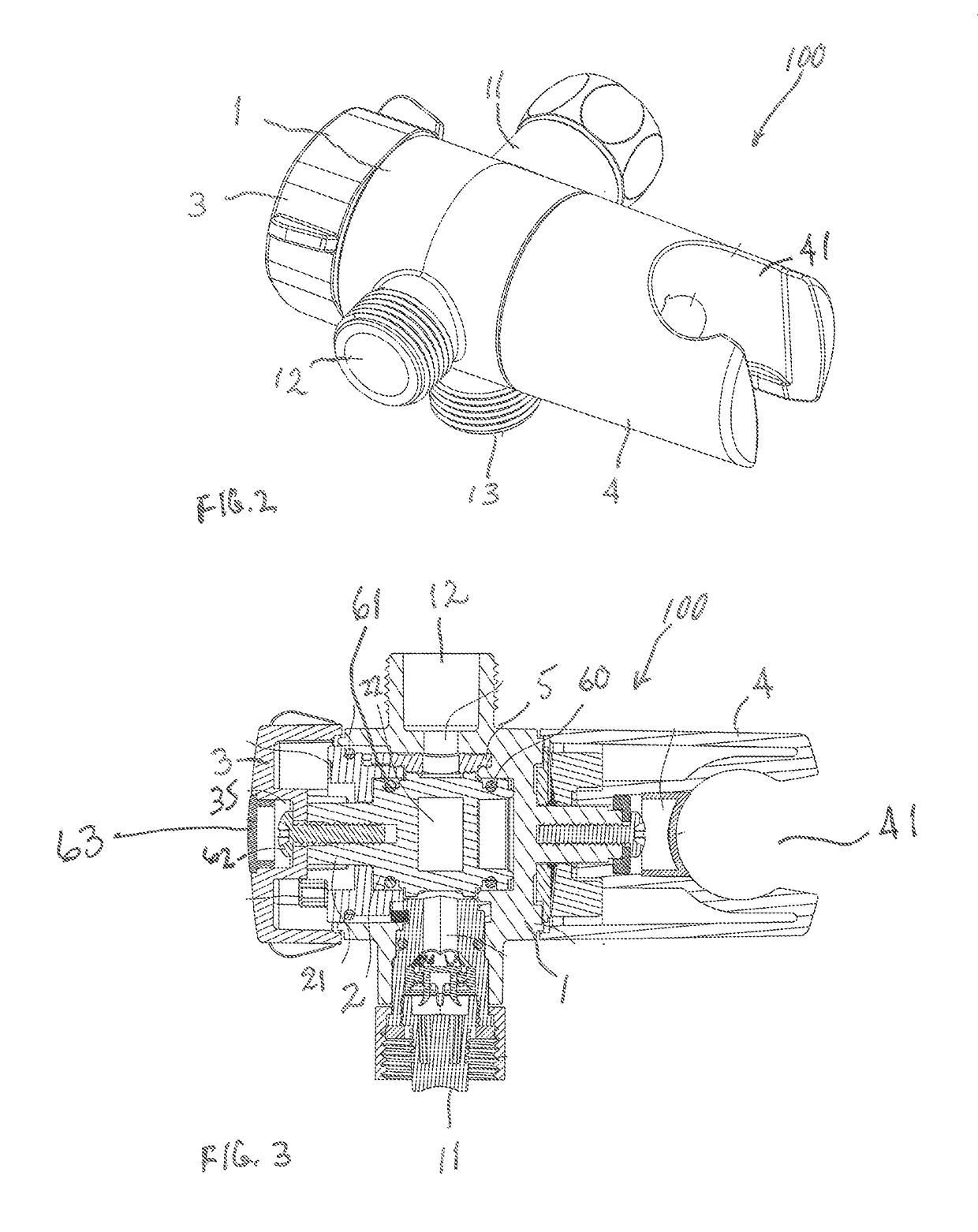
[0033]As may best be seen in FIG. 1, the diverter valve 100 of the invention includes a valve housing 1. FIGS. 1-3 depict a holder 4 that is secured to one side of the valve housing 1. As will be explained in more detail later, this holder 4 retains a hose and its related, hand-held showerhead to the valve housing 1 and the diverter valve 100 of the invention, when that showerhead is not in use.

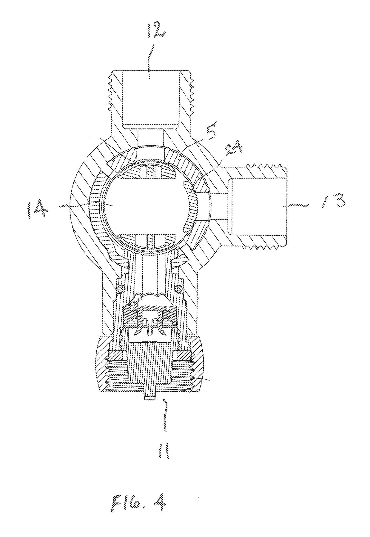
[0034]As may be seen in FIGS. 1, 2, and 4-7, the valve housing 1 includes a water inlet 11, a first water outlet 12, and a second water outlet 13. Water enters the valve housing 1 through the water inlet 11. Water leaves the valve housing 1 through one or both of the first water outlet 12 and the second water outlet 13.

[0035]FIGS. 1 and 3 show a valve core 2. As will be discussed in more detail below, valve core 2 assists in the control of water flow within the valve housing 1. Valve core 2 rotates along its...


PUM


Abstract

This invention relates to a diverter valve assembly, including a valve housing and a holder secured to the side of the housing for retaining a hand-held showerhead. The housing includes a water inlet port, and first and second water outlet ports. The valve housing includes a single internal valve cavity within which the hollow valve core rotates. The hollow valve core assists in diverting water within the valve cavity to one or both of the water outlet ports.

Description

TECHNICAL FIELD[0001]This invention relates to a diverter valve assembly that is installed in a water discharging fixture, such as a faucet or showerhead. The diverter valve assembly includes an inlet port, first and second outlet ports, and a valve assembly for controlling fluid flow to the first and second outlet ports.BACKGROUND OF THE INVENTION[0002]Diverter valves are in wide use in connection with the supply of water to faucets, showerheads, and similar water discharging fixtures. One common type of diverter valve currently in use includes a single inlet and two outlets. The single inlet is connected to a water supply hose, and water flows into the diverter valve through this hose and the inlet. The two outlets are connected to the water discharging fixtures. For example, one outlet may be connected to a wall-mounted, fixed showerhead, and the second outlet may be connected to a flex hose and a hand-held showerhead. A knob on the diverter can be swiveled between two or more po...

Claims


Application Information

Patent Timeline
Patent Type & Authority Applications(United States)
IPC IPC(8): E03C1/02F16K31/60F16K25/00F16K27/06
CPCE03C1/023F16K27/06F16K25/005F16K31/60F16K5/0471F16K11/0853F16K27/065
Inventor ZHU, CHUANBAO
Owner XIAMEN LOTA INT CO LTD
Why Eureka
Try Eureka