Large two-stroke compression-ignited internal combustion engine with fuel injection system for low flashpoint fuel and a fuel valve therefore

a fuel injection system and internal combustion engine technology, applied in the direction of fuel supply apparatus, fuel injecting pump, charge feed system, etc., can solve the problems of low flashpoint fuel, low fuel efficiency, and disadvantages of the fuel supply system of large two-stroke compression-ignited internal combustion engines

Active Publication Date: 2019-01-03
MAN ENERGY SOLUTIONS FILIAL AF MAN ENERGY SOLUTIONS SE TYSKLAND
View PDF5 Cites 9 Cited by
  • Summary
  • Abstract
  • Description
  • Claims
  • Application Information

AI Technical Summary

Benefits of technology

[0050]By providing a conduit connecting the low flashpoint fuel supply port to the said longitudinal bore at a second position, a position being closer to said fuel cavity than said first position of the sealing liquid, the high sealing oil does not have to seal against the boosted fuel pressure (injection pressure) of several hundred bar (which would require an even higher sealing liqui...

Problems solved by technology

However, there are problems associated with using a low flashpoint fuels in a large low-speed uniflow turbocharged two-stroke internal combustion engine.
One of those problems is the low flashpoint, which causes significant problems if low flashpoint fuel leaks into one of the other systems of the engine and mixes with another fluid, such as e.g. the lubrication oil system.
Thus, should low flashpoint find its way into another system of the engine it is necessary to stop the engine operation for safety reasons and to clean or replace all of the liquid in such a system, a costly and cumbersome affair for the operator of the engine.
The known common rail type gaseous fuel supply system for large two-stroke compression-ignited internal combustion engines have disadvantages when operating on LPG or any other similar low flashpoint fuel with a relatively high compressib...

Method used


Image

  • Large two-stroke compression-ignited internal combustion engine with fuel injection system for low flashpoint fuel and a fuel valve therefore
  • Large two-stroke compression-ignited internal combustion engine with fuel injection system for low flashpoint fuel and a fuel valve therefore
  • Large two-stroke compression-ignited internal combustion engine with fuel injection system for low flashpoint fuel and a fuel valve therefore

Examples


Embodiment Construction

[0066]In the following detailed description, an internal combustion engine will be described with reference to a large two-stroke low-speed turbocharged compression-ignited internal combustion engine with crossheads in the example embodiments, but it is understood that the internal combustion engine could be of another type, such as a two-stroke Otto, a four-stoke Otto or Diesel, with or without turbocharging, with or without exhaust gas recirculation.

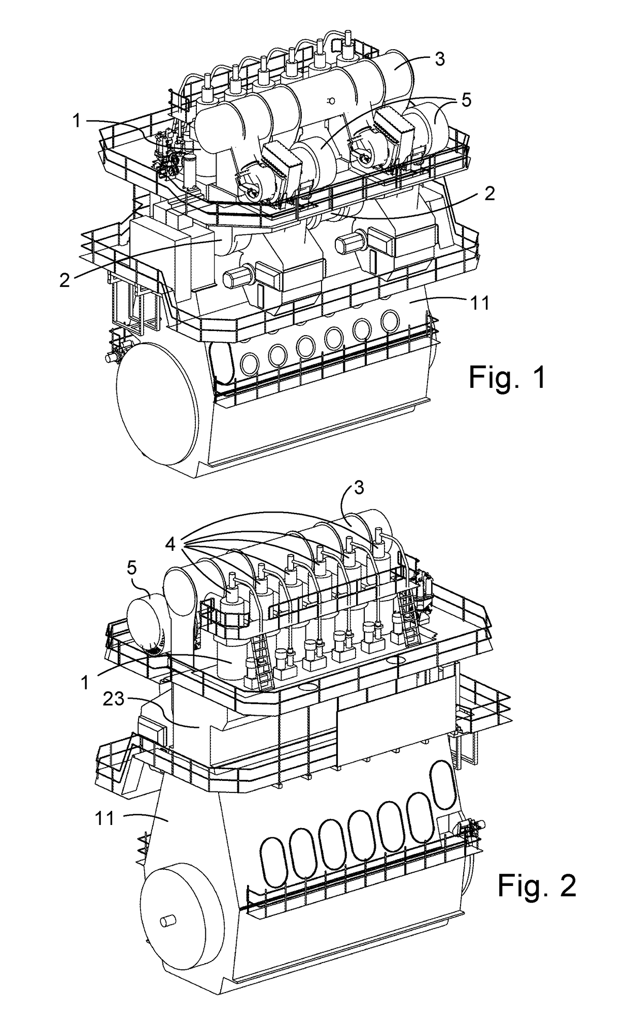
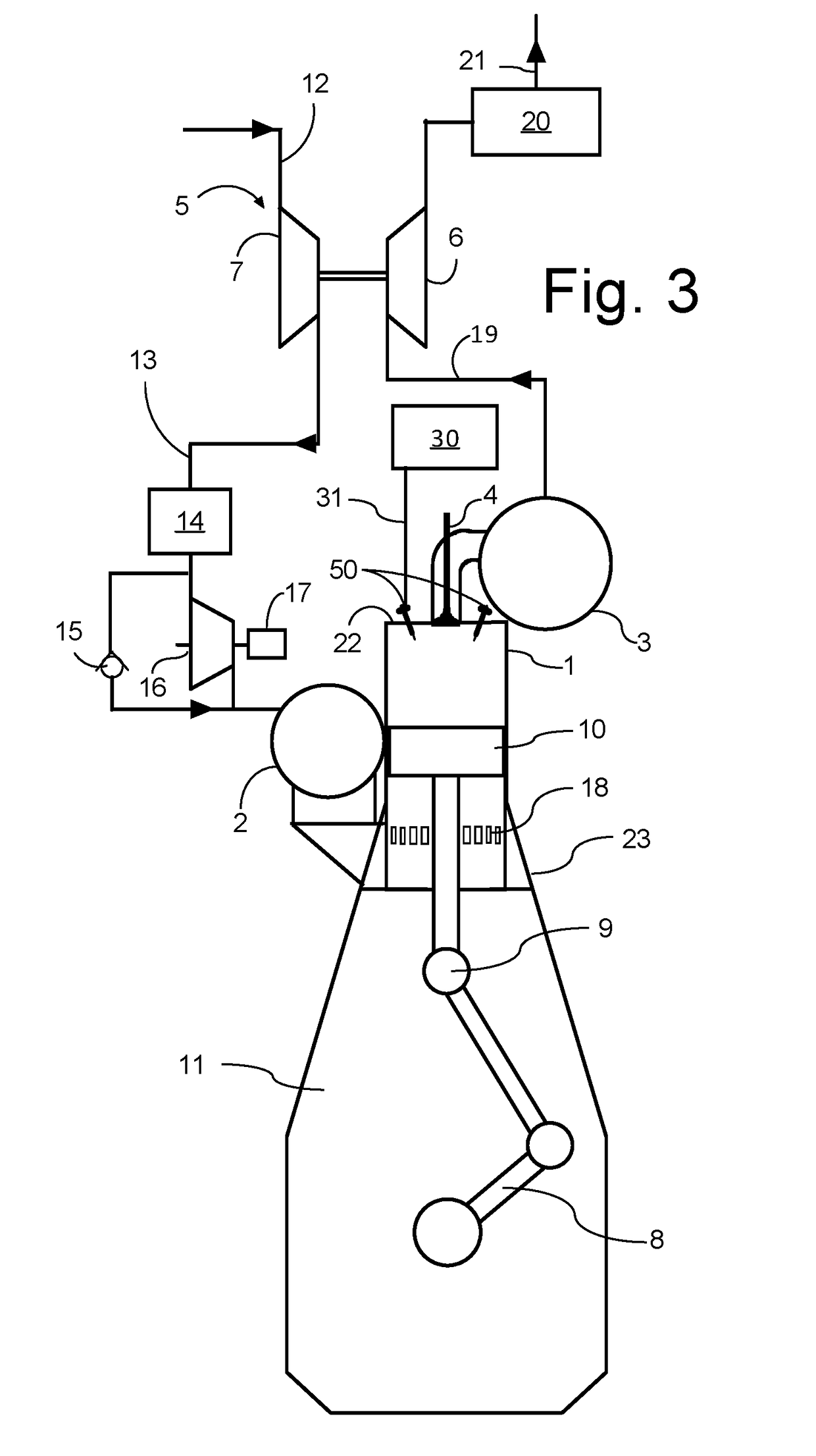
[0067]FIGS. 1, 2 and 3 show a large low-speed turbocharged two-stroke diesel engine with a crankshaft 8 and crossheads 9. FIG. 3 shows a diagrammatic representation of a large low-speed turbocharged two-stroke diesel engine with its intake and exhaust systems. In this example embodiment the engine has six cylinders in line. Large low-speed turbocharged two-stroke diesel engines have typically between four and fourteen cylinders in line, carried by a cylinder frame 23 that is carried by an engine frame 11. The engine may e.g. be used as...


PUM


Abstract

A large two-stroke turbocharged compression-ignited internal combustion crosshead engine with a plurality of cylinders has at least one pressure booster for each cylinder for boosting fuel pressure, two or more electronically controlled fuel valves for each cylinder with an inlet of the two or more electronically controlled fuel valves being connected to an outlet of the at least one pressure booster. An electronic control unit is connected to the at least one pressure booster and the two or more electronically controlled fuel valves. The electronic control unit is configured to determine a start time for a fuel injection event, activate the at least one pressure booster ahead of the determined start time and pen the two or more electronically controlled fuel valves at the determined start time.

Description

TECHNICAL FIELD[0001]The disclosure relates to large slow-running two-stroke compression-ignited internal combustion crosshead engines with a fuel injection system for injecting a low flashpoint fuel into the combustion chambers.BACKGROUND[0002]Large two-stroke uniflow turbocharged compression-ignited internal combustion crosshead engines are typically used in propulsion systems of large ships or as prime mover in power plants. The sheer size, weight and power output renders them completely different from common combustion engines and places large two-stroke turbocharged compression-ignited internal combustion engines in a class for themselves.[0003]Large two-stroke turbocharged compression-ignited internal combustion engines of the crosshead type are typically used in propulsion systems of large ships or as prime mover in power plants.[0004]Large two-stroke compression-ignited internal combustion engines are conventionally operated with a liquid fuel such as e.g. fuel oil or heavy ...

Claims


Application Information

Patent Timeline
IPC IPC(8): F02D19/06F02M55/00F02M63/00F02M57/02F02M59/00F02M61/00F02M43/02F02M43/04F02D19/10F02D29/06F02D41/00F02D41/38F02M59/46
CPCF02M55/002Y02T10/36F02D19/10F02D19/0686F02D2400/04F02D2041/389F02D41/0025F02D41/0007F02D29/06F02M57/026F02D41/38F02M43/04F02M63/00F02M61/00F02M59/00F02M55/005F02M59/464F02M43/02F02M55/004F02M63/0005F02M59/462F02D41/3005F02D41/3836F02D41/401F02M61/10F02M61/16F02M63/02F02M2200/953F02M2200/956F02D19/022F02D19/024F02M21/0263F02M21/0275F02M21/0212Y02T10/30Y02T10/12F02B75/20F02B75/02F02D41/3094F02D41/34F02M61/18F02B2275/14F02B2075/025F02M2200/16
Inventor KJEMTRUP, NIELSMAYER, STEFANHAGEN, PETER
Owner MAN ENERGY SOLUTIONS FILIAL AF MAN ENERGY SOLUTIONS SE TYSKLAND
Why Eureka
Try Eureka