Unlock instant, AI-driven research and patent intelligence for your innovation.

Electrical supply module

a technology of supply module and supply module, which is applied in the direction of lighting support device, coupling device connection, lighting and heating apparatus, etc., can solve the problems of only being able to shorten the strip by cutting, destroying the lighting system, and not providing much flexibility in the above documents, so as to achieve greater freedom of positioning and improve the life of the led

Active Publication Date: 2019-01-03
LED IBOND INT AS
View PDF1 Cites 2 Cited by
  • Summary
  • Abstract
  • Description
  • Claims
  • Application Information

AI Technical Summary

Benefits of technology

The invention is a lighting fixture that uses an electrical supply module with a plurality of adapters for powering electronic components, such as LEDs. The adapters can be positioned freely on the surface of the fixture, and the distance between them can range from 25 mm to 1000 mm. The module has a flexible design that allows for high luminous intensity at close distances or flexibility in the placement of adapters at 500 mm or more. The fixture also has a light processing layer made of a polymer panel or film to protect the electronic component. The invention is suitable for outdoor use or as a ceiling panel with a particular kind of light desired for different applications. The sealing makes the fixture water-tight, especially when the light processing layer is also used.

Problems solved by technology

However, neither of the above documents provides much flexibility since the fixtures cannot be modified with respect to size, especially with respect to the number of LED's.
However, shortening of the strip by cutting is only possible at specifically indicated sites.
Cutting the strip at other sites will destroy the lighting system.
Moreover, the strip is linear meaning that the flexibility will be limited to a single dimension, and further it is not possible to add additional LED's in an existing strip.

Method used


Image

  • Electrical supply module
  • Electrical supply module
  • Electrical supply module

Examples


Embodiment Construction

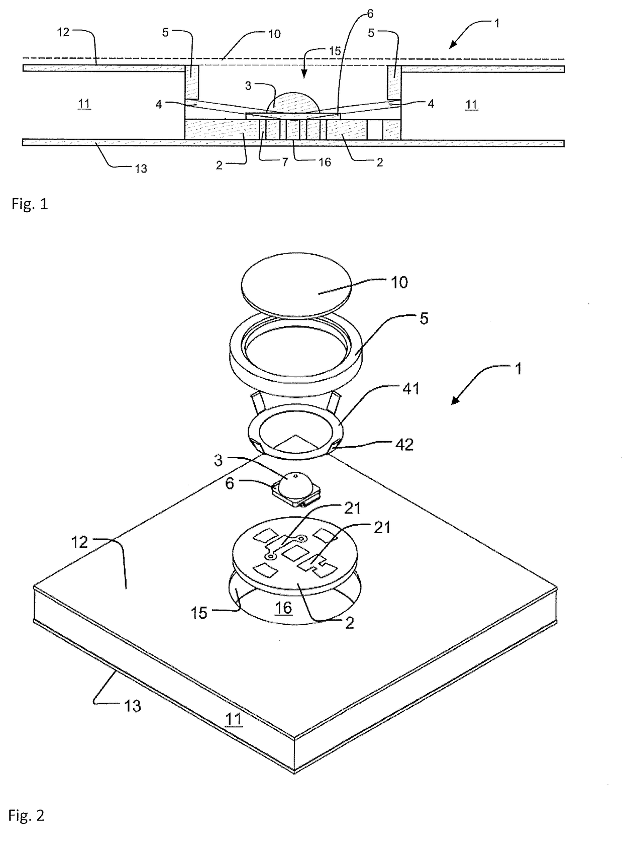
[0091]The present invention relates to an electrical supply module and electrical supply system, and to a lighting fixture, a lighting fixture system, a lighting fixture kit, and methods of producing an electrical supply module or a lighting fixture.

[0092]In a specific embodiment the electrical supply module is a lighting fixture, which employs light emitting diodes (LED) and can be used for general illumination. The lighting fixture provides flexibility for fitting into a spatially limited location by adjusting the size of the lighting fixture as desired. In the context of the invention the term “LED” may refer to a single LED or several, e.g. 2 to 10, serially connected LED's, unless otherwise noted. The LED is an example of an “electronic component” and the terms may be used interchangeably. However, an electronic component may also be another component than a LED. A LED will have a forward voltage (Vf) required to power the LED and make it light. The LED's are preferably white l...


PUM


Abstract

An electrical supply module including: a composite board including an anode layer and a cathode layer of electrically conducting material, which anode layer and cathode layer are separated by an insulator of electrically insulating material, the anode layer and the cathode layer each having a trench extending from a connection surface of the composite board; an adapter for mounting in a hole extending entirely through or partly through the composite board, the adapter including a circuit board carrying an electronic component, the circuit board establishing electrical connection from the anode layer to an anode of the electronic component and electrical connection from the cathode layer to a cathode of the electronic component; and a power supply capable of providing a constant voltage or a constant current between the anode layer and the cathode layer. An electrical supply system including the electrical supply module and an extension module.

Description

FIELD OF THE INVENTION[0001]The present invention relates to an electrical supply module comprising a composite board with two layers of an electrically conducting material separated by an insulator, an adapter for mounting in the composite board, and a power supply capable of providing power to the electrically conducting layers. The electrical supply module offers greater flexibility since the electrical supply module can be easily coupled to an extension module also based on a composite board. The invention also relates to an electrical supply system and to a lighting fixture.PRIOR ART[0002]Composite boards are well known construction elements for LED based lamps where two electrically conducting plates separated by an insulating material are used to supply electricity to and from LED's mounted in the composite board. Thus, WO 2003 / 017435 discloses an adapter for electrical power transfer for mounting in an aperture in such a composite board. The adapter comprises first pins esta...

Claims


Application Information

Patent Timeline
Patent Type & Authority Applications(United States)
IPC IPC(8): F21V23/02H01R25/14H01R31/06H01R13/24H01R43/26
CPCF21V23/02H01R25/147H01R31/06H01R13/2457H01R43/26F21Y2115/10F21V33/006F21S8/04F21V21/35F21W2121/008F21Y2105/10
Inventor FREDERIKSEN, LARS
Owner LED IBOND INT AS
Features
  • R&D
  • Intellectual Property
  • Life Sciences
  • Materials
  • Tech Scout
  • Unparalleled Data Quality
  • Higher Quality Content
  • 60% Fewer Hallucinations
Learn More