

Light source apparatus and projection display apparatus
- Summary
- Abstract
- Description
- Claims
- Application Information
AI Technical Summary
Benefits of technology
Problems solved by technology
Method used
Image

Examples
first exemplary embodiment
[0017]The projection display apparatus in accordance with the first embodiment is demonstrated hereinafter with reference to FIG. 1-FIG. 3.
[Projection Display Apparatus]
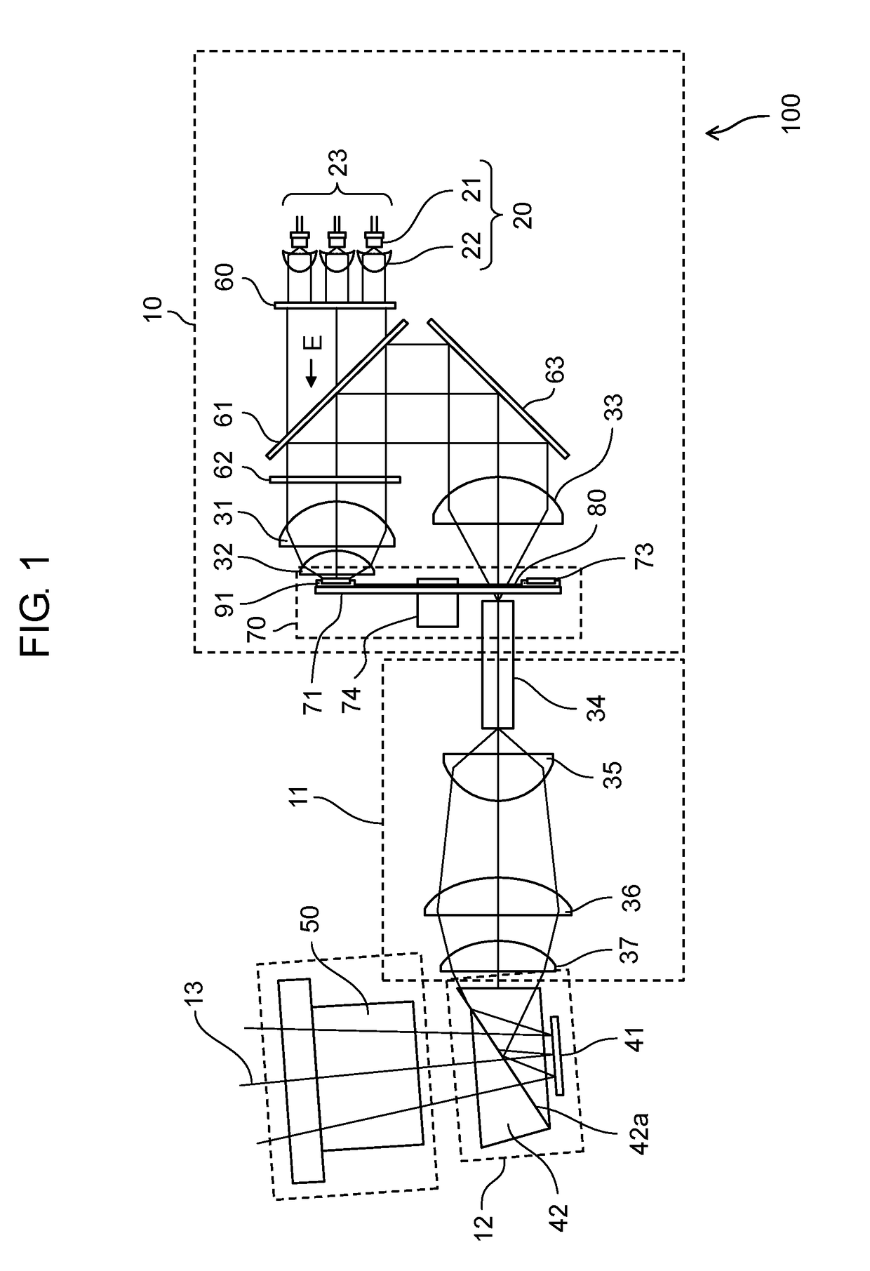
[0018]FIG. 1 illustrates an optical structure, among others, of projection display apparatus 100 in accordance with the first embodiment. Projection display apparatus 100 employs one spatial modulating element, i.e. DMD (Digital Mirror Device) 41 for modulating light in response to an image signal.
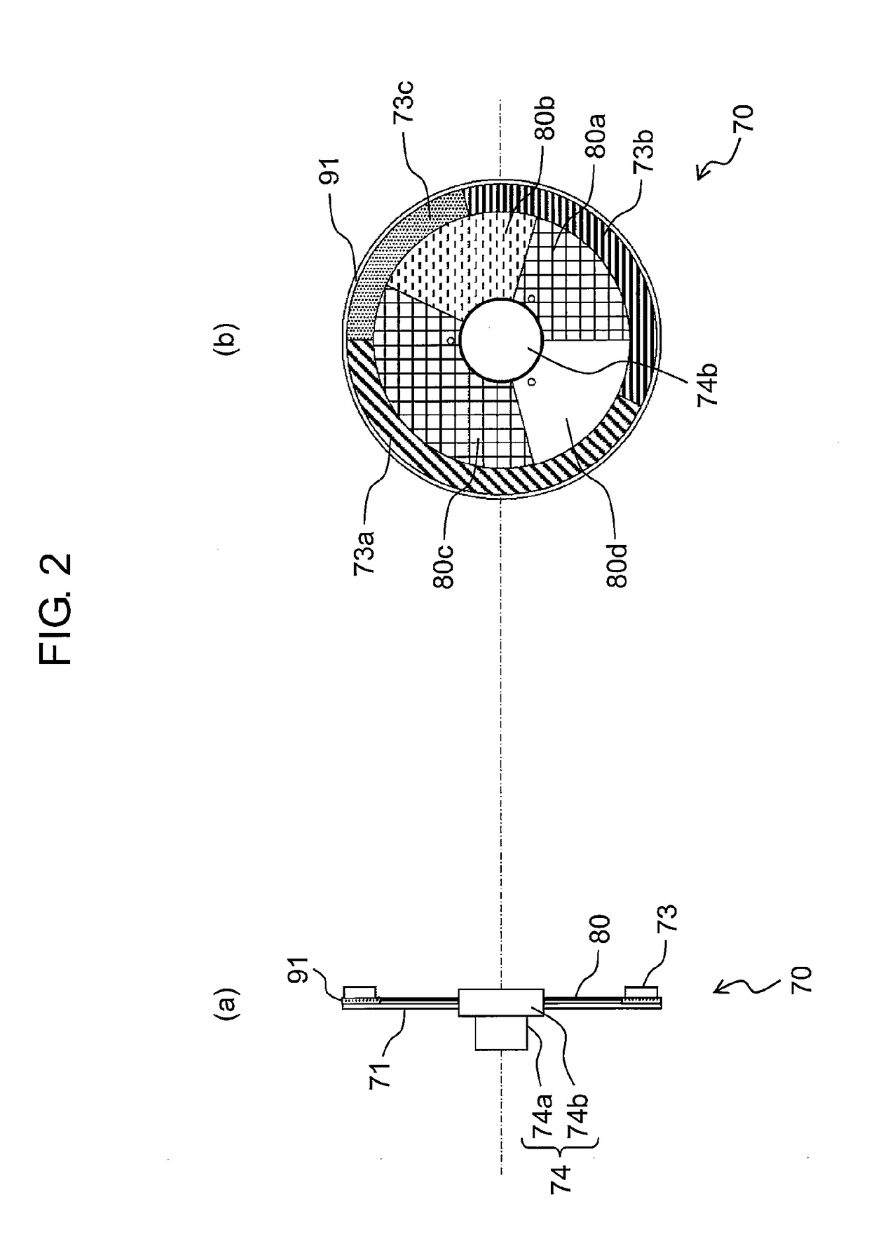
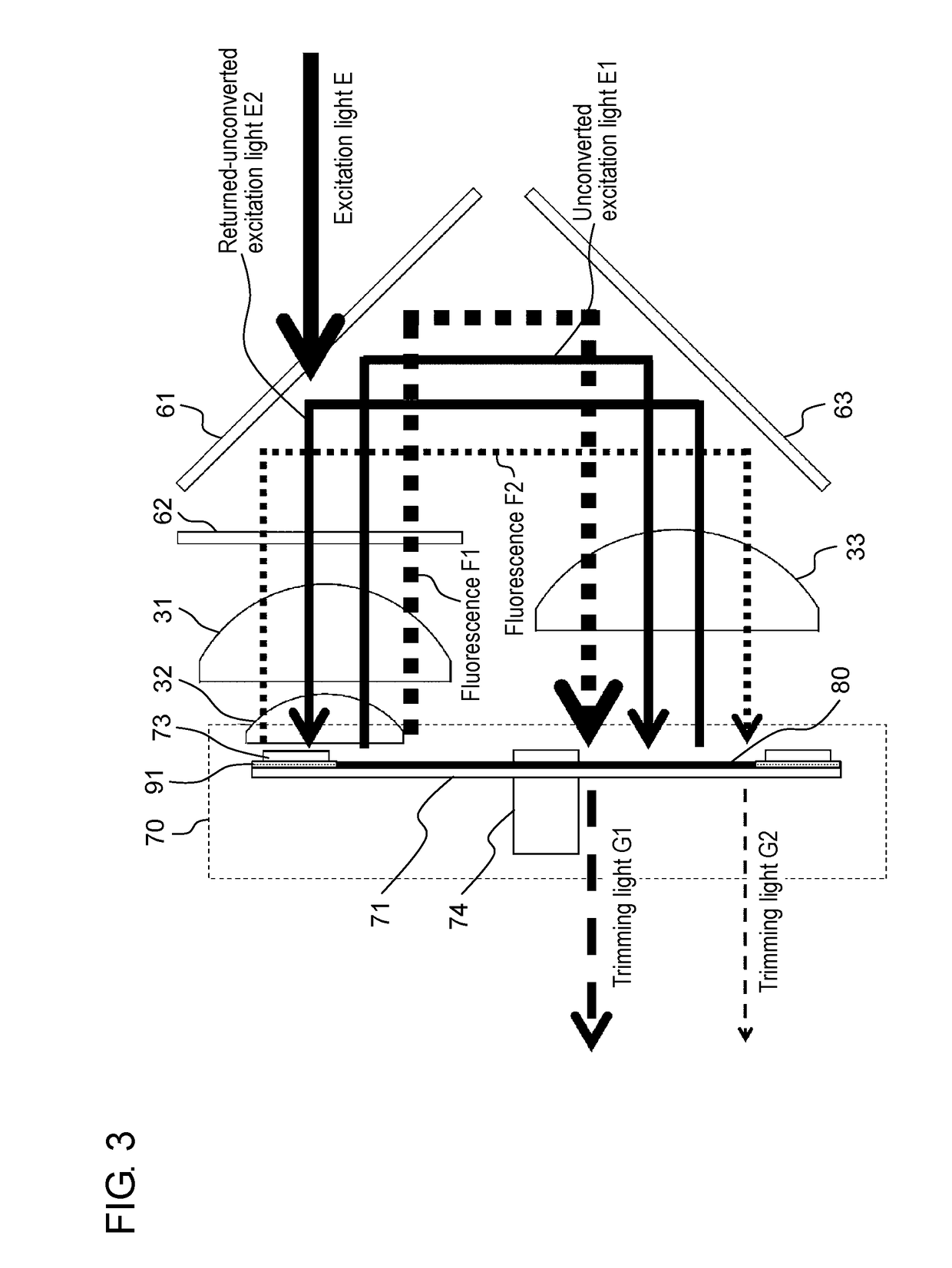
[0019]As shown in FIG. 1, projection display apparatus 100 includes the following structural elements:[0020]light source 20;[0021]light source apparatus 10 formed of phosphor wheel 70 and optical filter 80;[0022]lighting apparatus 11 casting an outgoing-beam from light source apparatus 10 to DMD 41 (i.e. spatial modulating element);[0023]image display section 12, and[0024]projecting section 13 projecting image-light (video) produced in image display section 12 onto a screen (not shown).
Light source apparatus 10 emits refere...
second exemplary embodiment
[0073]FIG. 4 shows a structure of projection display apparatus 101 in accordance with the second embodiment of the present disclosure. As FIG. 4 shows, projection display apparatus 101 includes light source apparatus 111, lighting apparatus 11, image display section 12, and projecting section 13. Lighting apparatus 11, image display section 12, and projecting section 13 stay the same as those of projection display apparatus 100 in accordance with the first embodiment. In the description below, structural elements similar to those shown in FIG. 1 have the same reference marks. Detailed and duplicated descriptions of those elements are omitted here. Different points from the first embodiment are chiefly described hereinafter.
[0074]Light source apparatus 10 in accordance with the first embodiment includes optical filter 80 on the rotary shaft side (i.e. between reflective coating 91 and motor 74). This structure is effective for downsizing the optical system. On the other hand, light s...
PUM
 Abstract
Description
Claims
Application Information