Fuel cell system and method of controlling fuel cell system

a fuel cell and system technology, applied in the direction of secondary cell servicing/maintenance, battery/fuel cell control arrangement, etc., can solve the problems of normal fuel cell unit overloaded, limited output of fuel cell unit, and inability to discharge secondary batteries, etc., to suppress the rise in fuel cell temperature, reduce deviation, and enhance the cooling capacity of the fuel cell cooling mechanism

Active Publication Date: 2019-01-03
TOYOTA JIDOSHA KK
View PDF13 Cites 6 Cited by
  • Summary
  • Abstract
  • Description
  • Claims
  • Application Information

AI Technical Summary

Benefits of technology

[0015]In the fuel cell system of the above aspect, when a difference by subtracting the temperature of the converter included in the first fuel cell unit from the temperature of the converter included in the second fuel cell unit is equal to or greater than a reference value, the control unit included in the second fuel cell unit may perform a process to cool down the converter included in the second fuel cell unit. This configuration further reduces a deviation with regard to the temperature of the converter.
[0016]In the fuel cell system of the above aspect, when a difference by subtracting the temperature of the secondary battery included in the first fuel cell unit from the temperature of the secondary battery included in the second fuel cell unit is equal to or greater than a reference value, the control unit included in the second fuel cell unit may perform a process to cool down the secondary battery included in the second fuel cell unit. This configuration further reduces a deviation with regard to the temperature of the secondary battery.
[0017]According to another aspect of the present disclosure, there is provided a fuel cell system comprising a first fuel cell unit and a second fuel cell unit. Each of the first fuel cell unit and the second fuel cell unit comprises a fuel cell; and a control unit configured to control power generation of the fuel cell. The control unit included in the first fuel cell unit performs a control using a control target with regard to a temperature of the fuel cell included in the first fuel cell unit. The control unit included in the second fuel cell unit performs a control using a control target with regard to a temperature of the fuel cell included in the second fuel cell unit. When the temperature of the fuel cell included in the first fuel cell unit reaches a reference value that is larger than a maximum value of the control target, the control unit included in the first fuel cell unit limits electric power generated by the fuel cell included in the first fuel cell unit. When the 1 power generated by the fuel cell included in the first fuel cell unit is limited, the control unit included in the second fuel cell unit makes compensation to compensate for at least part of a deficient power by the limitation with a power generated by the fuel cell included in the second fuel cell unit. The control targets used by the control unit included in the first fuel cell unit and by the control unit included in the second fuel cell unit have numerical ranges that at least partly overlap with each other. This configuration prevents the occurrence of a deviation with regard to the temperature of the fuel cell.
[0018]In the fuel cell system of the above aspect, the second fuel cell unit may further comprise a fuel cell cooling mechanism configured to cool down the fuel cell. The control unit included in the second fuel cell unit may enhance a cooling capacity of the fuel cell cooling mechanism, when the compensation is made. This configuration suppresses a temperature rise of the fuel cell when the compensation is made.
[0019]The fuel cell system of the above aspect may be mounted on a machine having a moving function. The fuel cell cooling mechanism may include a radiator. The control unit included in the second fuel cell unit may determine an upper limit of the power generated by the fuel cell included in the second fuel cell unit, based on a cooling capacity of the radiator that is estimated from an ambient temperature and a moving speed of the machine, when the compensation is made. This configuration adequately controls the heat value based on the cooling capacity of the radiator and thereby suppresses the temperature of the fuel cell from becoming excessively high.
[0020]In the fuel cell system of the above aspect, when a difference by subtracting the temperature of the fuel cell included in the second fuel cell unit from the temperature of the fuel cell included in the first fuel cell unit is equal to or greater than a reference value, the control unit included in the first fuel cell unit may perform a process to cool down the fuel cell included in the first fuel cell unit. This configuration further reduces a deviation with regard to the temperature of the fuel cell.

Problems solved by technology

For example, when the SOC of a secondary battery included in one fuel cell unit reaches a lower limit value, this secondary battery is not allowed to be discharged.
Thus the output from the fuel cell unit is limited to only the power generated by the fuel cell.
Continuing such compensation, however, the normal fuel cell unit is overloaded.
This is likely to cause an output of the normal fuel cell unit being also limited and interfere with the operation of the fuel cell system.
Limitation of the compensation by the normal fuel cell unit may causes a failure to meet an output request.
The original cause of such a failure is attributed to a failure in preventing a deterioration of a control parameter (for example, SOC) in the part of the fuel cell units.

Method used


Image

  • Fuel cell system and method of controlling fuel cell system
  • Fuel cell system and method of controlling fuel cell system
  • Fuel cell system and method of controlling fuel cell system

Examples


embodiment 1

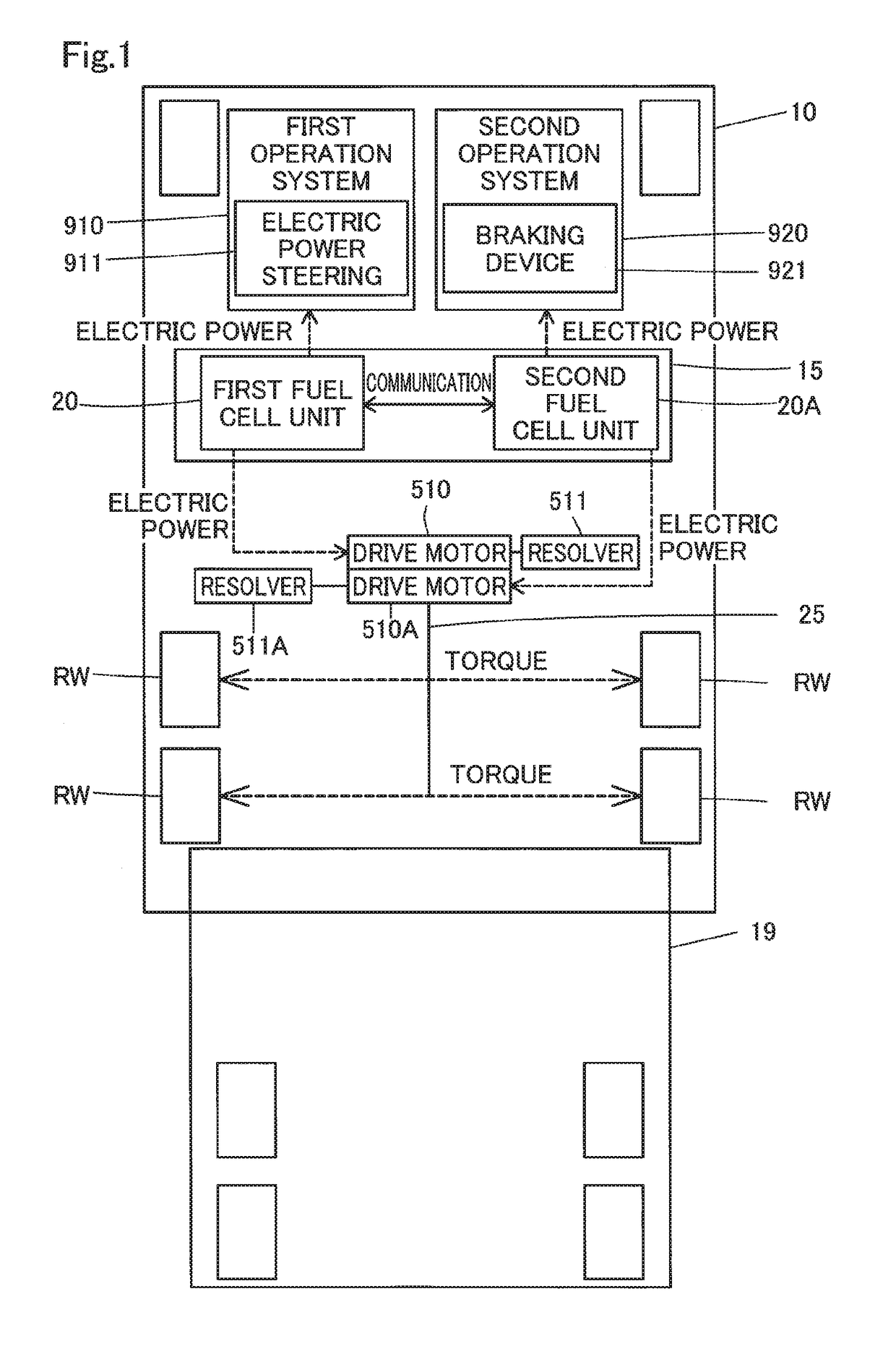
[0039]The following describes FIG. 1 illustrates a fuel cell vehicle 10. The fuel cell vehicle 10 is a motor truck pulling a trailer 19. The fuel cell vehicle 10 includes a fuel cell system 15, a propeller shaft 25, a drive motor 510, a drive motor 510A, a resolver 511, a resolver 511A, a first operation system 910 and a second operation system 920. The fuel cell system 15 is comprised of a first fuel cell unit 20 and a second fuel cell unit 20A.

[0040]The first operation system 910 and the second operation system 920 collectively designate devices operated by the driver for driving. The first operation system 910 receives power supply from the first fuel cell unit 20. The second operation system 920 receives power supply from the second fuel cell unit 20A. The first operation system 910 includes an electric power steering 911. The second operation system 920 includes a braking device 921. Both the electric power steering 911 and the braking device 921 consume electric power.

[0041]T...

embodiment 2

[0133]In Embodiment 2, in order to further decrease the frequency of the output limitations, the control units 600 and 600A perform processes to positively eliminate a deviation with regard to each of various parameters.

[0134]FIG. 11 is a flowchart showing a deviation eliminating process for the SOC. The control unit 600 determines whether a deviation occurs with regard to the SOC (S610). The occurrence of the deviation means that a difference by subtracting the SOC of the secondary battery 550 included in the first fuel cell unit 20 from the SOC of the secondary battery 550A included in the second fuel cell unit 20A is equal to or greater than a reference value. The reference value is a positive value. The necessary condition to make the above difference equal to or greater than the reference value is that the SOC of the secondary battery 550A is higher than the SOC of the secondary battery 550.

[0135]Accordingly, when the difference by subtracting the SOC of the secondary battery 5...


PUM

PropertyMeasurementUnit
electric poweraaaaaaaaaa
poweraaaaaaaaaa
cooling capacityaaaaaaaaaa

Abstract

A control unit included in a first fuel cell unit stores a target range set. The target range set includes an SOC control target range, a control target range of temperature of a secondary battery, a control target range for FC temperature, a control target range for temperature of a BDC, a control target range for temperature of a hydrogen pump, and a control target range for temperature of an air compressor. The control unit controls the respective parameters to fall within these target ranges. A control unit included in a second fuel cell unit also stores the target range set. The control unit included in the second fuel cell unit thus similarly controls the respective parameters to fall within the same target ranges, like the control unit included in the first fuel cell unit.

Description

CROSS-REFERENCE TO RELATED APPLICATIONS[0001]The present application claims priority to Japanese patent application No. 2017-127132 filed on Jun. 29, 2017, the entirety of the content of which is hereby incorporated by reference into this application.BACKGROUND ART[0002]The present disclosure relates to control of a fuel cell.[0003]JP 2016-054600A discloses a motor vehicle mounts on two fuel cell units (driving mechanisms). When an abnormality occurs in one of the two fuel cell units, the motor vehicle disclosed in JP 2016-054600A causes only a secondary battery included in the normal fuel cell unit to be charged with regenerative power and thereby avoids SOC (state of charge) of the secondary battery included in the normal fuel cell unit from becoming excessively high.[0004]In a configuration of a fuel cell system comprised of a plurality of fuel cell units, an output may be limited on each of the fuel cell units. For example, when the SOC of a secondary battery included in one fue...

Claims


Application Information

Patent Timeline
Patent Type & Authority Applications(United States)
IPC IPC(8): H01M8/04701H01M8/0432H01M10/44H01M10/613H02J7/00
CPCH01M8/04701H01M8/0432H01M10/44H01M10/613H02J7/0091H02J2007/0059H01M10/48H01M10/486H01M16/006H01M8/04007H01M8/04731H01M2220/20H01M2250/20H02J7/34H02J2300/30H02J2310/48H02J1/00Y02T10/7072Y02T90/14H02J7/007194Y02E60/50B60L53/20B60L53/11B60L58/30H01M8/04626H01M8/04738H01M8/04925H01M8/04947B60L2240/525H02J2207/20H02J7/007192
Inventor NADA, MITSUHIRO
Owner TOYOTA JIDOSHA KK
Why Eureka
Try Eureka