Supercharge Your Innovation With Domain-Expert AI Agents!

Drive sprocket assembly for a tracked machine

a technology of sprocket and drive assembly, which is applied in mechanical equipment, transportation and packaging, hoisting equipment, etc., can solve the problems of increased repair time, increased machine downtime, labor cost, and increased wear of the sprock

Active Publication Date: 2019-01-24
CATERPILLAR INC
View PDF5 Cites 2 Cited by
  • Summary
  • Abstract
  • Description
  • Claims
  • Application Information

AI Technical Summary

Benefits of technology

The present disclosure provides a drive sprocket assembly for an electric rope shovel. The assembly includes a hub with a raised portion and at least one first segment and one second segment that are removably affixed to the hub. The segments have a top surface and an inner surface that includes a first portion, a second portion, a third portion, and a fourth portion that abut the raised portion and the outer surface of the hub. The assembly also includes a tooth segment on the top surface of each segment for engagement with the track of the shovel. The technical effect of the invention is to provide a reliable and durable drive sprocket assembly for the electric rope shovel that ensures efficient and effective operation.

Problems solved by technology

The sprocket may experience accelerated wear due to friction mainly due to repeated contact with the track, contact with debris deposited around the sprocket, operation in harsh environment with the ground, and so on.
As a result, in such a situation, the drive assembly may have to completely dismantled in order to disassembly the dive shaft along with the bearings for providing access to the sprocket.
This may lead to increased repair time, machine downtime, labor cost, physical effort, and so on.
This may provide limited dismantling of the drive assembly in order to disassemble the drive shaft and the sprocket from the drive assembly without the bearings.
However, the loose fit may result in increased shaft movement, increased seal movement, increased noise and / or increased friction between contacting surfaces of the drive shaft and bearings, such as an outer surface of the drive shaft and an inner surface of the bearings, and so on.
As a result, the drive shaft, the bearings, the seals, drive couplings, and so on may experience accelerated wear leading to frequent replacement, increased replacement costs, and so on.
Also, in some situations, one or more teeth or sections of the sprocket may be worn out or damaged prior to remaining teeth or sections of the sprocket which may have some usable life remaining before complete wear of the sprocket.
In such a situation, the complete sprocket may have to be replaced, in turn, leading to reduce component usability, increased replacement cost, and so on.

Method used


Image

  • Drive sprocket assembly for a tracked machine
  • Drive sprocket assembly for a tracked machine
  • Drive sprocket assembly for a tracked machine

Examples


Embodiment Construction

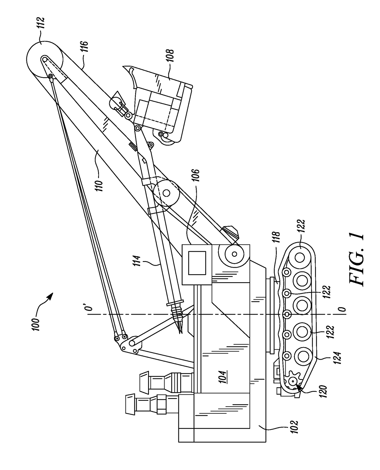
[0016]Wherever possible, the same reference numbers will be used throughout the drawings to refer to the same or the like parts. Referring to FIG. 1, an exemplary machine 100 is illustrated. More specifically, the machine 100 is an electric rope shovel. In other embodiments, the machine 100 may be any other tracked machine, such as a track type tractor, a hydraulic excavator, and so on. The machine 100 may be associated with any industry, including, but not limited to, construction, mining, agriculture, material handling, and transportation.

[0017]The machine 100 includes a frame 102. The frame 102 supports one or more components of the machine 100. The machine 100 includes an enclosure 104 provided on the frame 102. In one embodiment, the enclosure 104 may house a power source (not shown) therein mounted on the frame 102. The power source may be any power source known in the art, such as an internal combustion engine, batteries, motor, and so on, and / or a combination thereof. The po...


PUM


Abstract

A drive sprocket assembly is provided. The drive sprocket assembly includes at least one first segment and at least one second segment. Each of the at least one first segment and the at least one second segment is adapted to be removably affixed to a hub of the drive sprocket assembly. Each of the at least one first segment and the at least one second segment includes a top surface and an inner surface extending away from the top surface. The inner surface includes a stepped configuration. The inner surface is adapted to at least partially abut a raised portion of the hub and an outer surface of the hub. The drive sprocket assembly also includes a tooth segment provided on the top surface of each of the at least one first segment and the at least one second segment respectively.

Description

TECHNICAL FIELD[0001]The present disclosure relates to a drive sprocket assembly for a tracked machine. More particularly, the present disclosure relates to the drive sprocket assembly for a drive assembly of a tracked machine.BACKGROUND[0002]Generally, a tracked machine, such as an electric rope shovel, includes a drive assembly for transferring motive power from one or more of an engine, an electric motor, and / or a transmission system to a ground engaging track of the machine. In some embodiments, the drive assembly includes a sprocket mounted on a drive shaft thereof. In other embodiments, the sprocket may be mounted on a final drive planetary assembly. The sprocket provides interconnection with the track and transfer of motive power therebetween.[0003]The sprocket may experience accelerated wear due to friction mainly due to repeated contact with the track, contact with debris deposited around the sprocket, operation in harsh environment with the ground, and so on. As a result, ...

Claims


Application Information

Patent Timeline
Patent Type & Authority Applications(United States)
IPC IPC(8): B62D55/125F16H55/12F16H55/30B62D55/06
CPCB62D55/125F16H55/12E02F3/308B62D55/06F16H55/30B62D55/13
Inventor BLINDT, TODD MICHAEL
Owner CATERPILLAR INC
Features
  • R&D
  • Intellectual Property
  • Life Sciences
  • Materials
  • Tech Scout
  • Unparalleled Data Quality
  • Higher Quality Content
  • 60% Fewer Hallucinations
Learn More