
Multi-beam MIMO antenna systems and methods

a technology of antenna system and beam, applied in the field of communication devices, can solve the problems of low isolation, signal degradation, and interference between the mimo antenna and the other, and achieve the effects of improving the communication system capacity, high isolation, and enhancing the performance of the mimo

Active Publication Date: 2019-01-24
MATSING PTE
View PDF10 Cites 11 Cited by
  • Summary
  • Abstract
  • Description
  • Claims
  • Application Information

AI Technical Summary

Benefits of technology

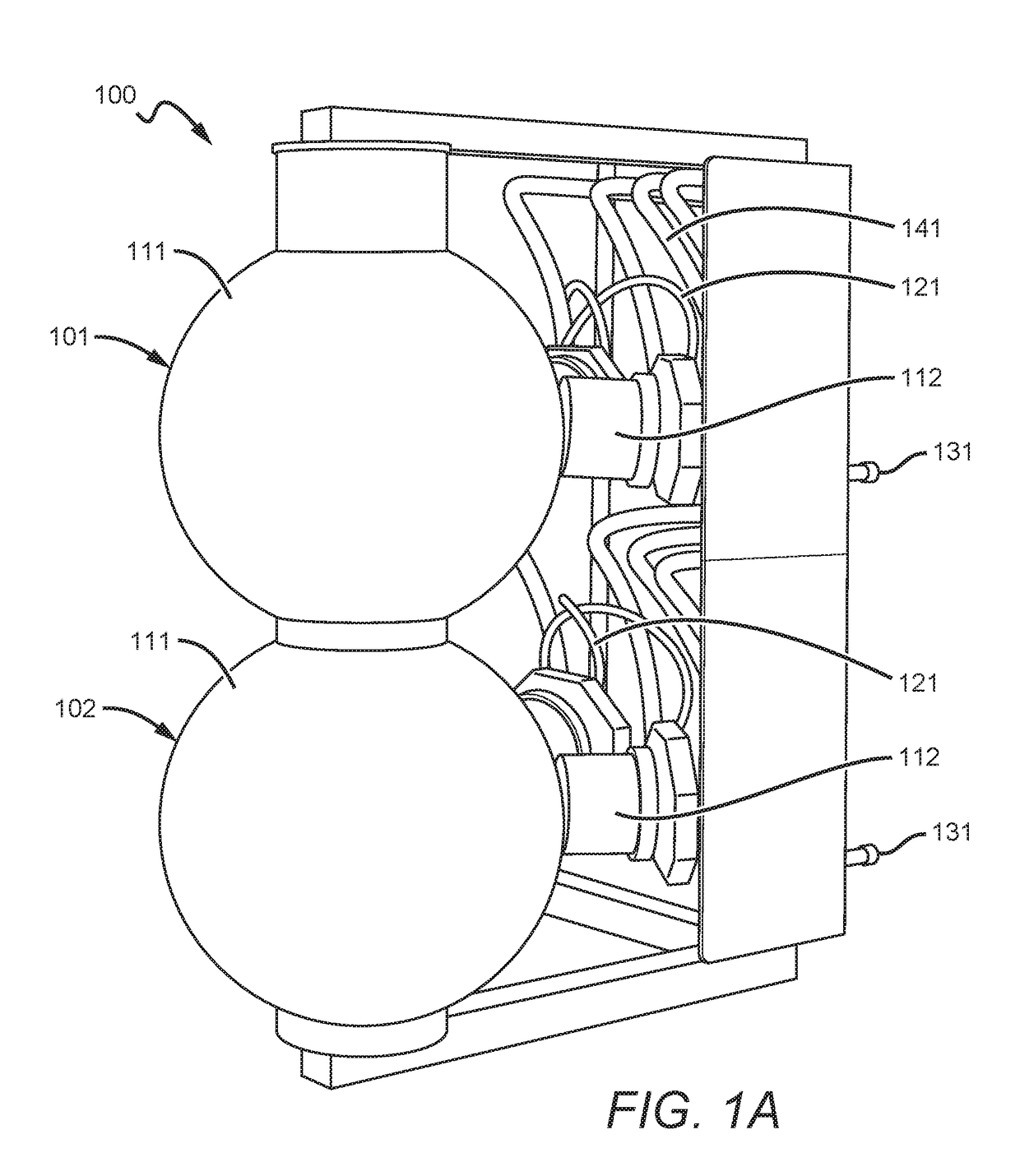
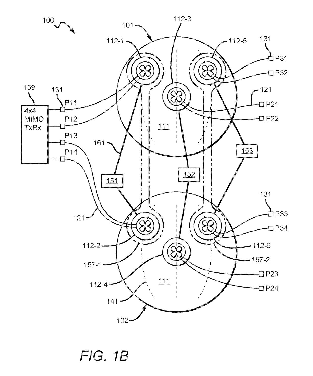
The use of a spherical RF lens allows for a combination of MIMO and multi-beam technologies, resulting in a much larger capacity for communication systems compared to other solutions. The spherical lens is ultra-wideband, compatible with MIMO transceivers, and has the unique feature of high isolation between ports, which greatly improves MIMO performance. Spherical lens antennas can be used as building blocks for multi-beam antennas with high-order MIMO.

Problems solved by technology

However, MIMO antennas produce signals that can interfere with one another without high isolation between antenna ports (See, “MIMO Processing for 4G and Beyond: Fundamentals and Evolution” by Mario Marques da Silva, Francisco A. Monteiro, CRC Press, 2014).
However, Hartenstein's absorber causes signal degradation and passive inter-modulation (PIM) issues, which is not acceptable for 3G, 4G / LTE cellular systems.
Other MIMO antennas, such as those disclosed in US 2011 / 0135308 to Tarlazzi et. al., are quite bulky and are not multi-beam.
However, existing multi-beam antennas cannot be used effectively with MIMO systems because of poor isolation between antenna ports.
Antenna ports in other attempted solutions typically exhibit 13-15 dB isolation, which is not enough for a wide operational frequency band.
Therefore, existing multi-beam antennas attempted by others cannot provide wideband MIMO performance required for current and future cellular communications, and existing MIMO antennas are not suitable for multi-beam operation.

Method used


Image

  • Multi-beam MIMO antenna systems and methods
  • Multi-beam MIMO antenna systems and methods
  • Multi-beam MIMO antenna systems and methods

Examples


Embodiment Construction

[0067]In some embodiments, the numbers expressing quantities of ingredients, properties such as concentration, reaction conditions, and so forth, used to describe and claim certain embodiments of the invention are to be understood as being modified in some instances by the term “about.” Accordingly, in some embodiments, the numerical parameters set forth in the written description and attached claims are approximations that can vary depending upon the desired properties sought to be obtained by a particular embodiment. In some embodiments, the numerical parameters should be construed in light of the number of reported significant digits and by applying ordinary rounding techniques. Notwithstanding that the numerical ranges and parameters setting forth the broad scope of some embodiments of the invention are approximations, the numerical values set forth in the specific examples are reported as precisely as practicable. The numerical values presented in some embodiments of the invent...


PUM


Abstract

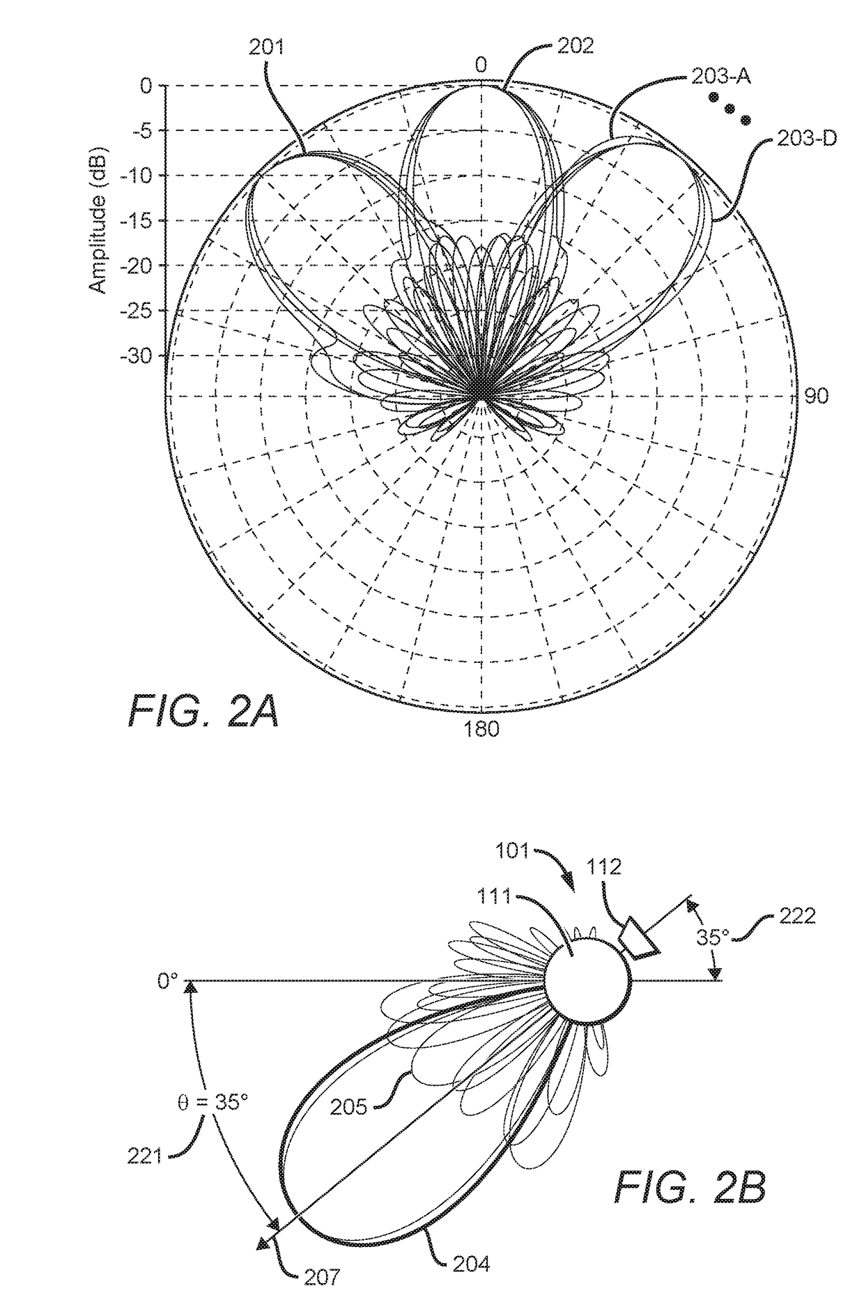
This application proposes multi-beam antenna systems using spherical lens with high isolation between antenna ports and compatible to 2×2, 4×4, 8×8 MIMO transceivers. Several compact multi-band, multi-beam solutions (with wideband operation, 40%+, in each band) are achieved by creating dual-band radiators movable on a track around one or more spherical lenses and by placing lower band radiators between spherical lenses. By using secondary lenses for high band radiators, coupling between low band and high band radiators is reduced. Beam tilt range and side lobe suppression are improved through phase shifting and / or a rotational angle of radiators. A wide beam tilt range (0-40 degree) can be achieved via the proposed multi-beam antenna systems. Each beam can be independently tilted. Based on proposed single and multi-lens antenna solutions, cell coverage improvements and stadium tribune coverage optimization are also achieved, together with a reduction in interference.

Description

CROSS-REFERENCE TO RELATED APPLICATIONS[0001]This application claims the benefit of priority to U.S. provisional application Ser. No. 62 / 445,874 filed Jan. 13, 2017, titled “MULTI-BEAM MIMO ANTENNA SYSTEMS AND METHODS” and to U.S. provisional application Ser. No. 62 / 538,615 filed Jul. 28, 2017 titled “Multi-Beam MIMO Antenna Systems and Methods.” These and all other extrinsic references referenced herein are incorporated by reference in their entirety. Where a definition or use of a term in an incorporated reference is inconsistent or contrary to the definition of that term provided herein, the definition of that term provided herein applies and the definition of that term in the reference does not apply.FIELD OF THE INVENTION[0002]The field of the invention is communication devices.BACKGROUND[0003]The following description includes information that may be useful in understanding the present invention. It is not an admission that any of the information provided herein is prior art o...

Claims


Application Information

Patent Timeline
Patent Type & Authority Applications(United States)
IPC IPC(8): H01Q1/52H01Q21/06H01Q19/06H01Q5/30H01Q21/00H01Q19/10H01Q3/36
CPCH01Q25/00H01Q15/08H01Q1/22H04B7/0408H04B7/0413H01Q1/2291H01Q3/14H01Q3/24H01Q3/30H01Q19/062H01Q25/001H01Q1/246H04L27/2647
Inventor MATITSINE, SERGUEITIMOFEEV, IGORMATYTSINE, LEONIDDEMARCO, ANTHONY
Owner MATSING PTE
Learn More