Supercharge Your Innovation With Domain-Expert AI Agents!

Assembly apparatus for forming an interfay joint during manufacture of an aircraft

a technology for aircraft and assembly equipment, applied in the direction of applications, domestic objects, wings, etc., can solve the problems of labour-intensive operation and time-consuming, and achieve the effect of minimising the volume of uncured shims required by the bath

Active Publication Date: 2019-01-31
AIRBUS OPERATIONS LTD
View PDF0 Cites 4 Cited by
  • Summary
  • Abstract
  • Description
  • Claims
  • Application Information

AI Technical Summary

Benefits of technology

The patent text describes a method to increase the production rate and simplify the process of shimming. This is achieved by using a gap between the joint components, which allows a shim material to adhere correctly. The size of the gap can vary depending on the desired thickness of the shim, but a minimum of 0.3 mm is usually required. The use of a gap helps to reduce the amount of uncured shim required by the bath, further minimizing the production process.

Problems solved by technology

As such, this operation is labour intensive and time consuming.

Method used


Image

  • Assembly apparatus for forming an interfay joint during manufacture of an aircraft
  • Assembly apparatus for forming an interfay joint during manufacture of an aircraft
  • Assembly apparatus for forming an interfay joint during manufacture of an aircraft

Examples


Embodiment Construction

)

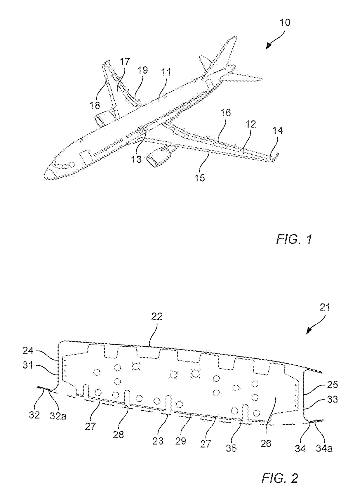
[0057]An aircraft 10 is shown in FIG. 1. The aircraft 10 includes a fuselage 11. Two wings 12 extend from the fuselage 11. It will be appreciated that the fuselage 11 and wings 12 may take a variety of different planned formed shapes and profiles depending on the particular application. Each wing 12 has a wing root 13 at the juncture with the fuselage 11 and a wing tip 14 at a distal end. The wing 12 has a leading edge 15 and a trailing edge 16. The wing 12 comprises a wing box 17. The wing box forms the main body of the wing 12. The wing 12 also comprises a leading edge assembly 18 and a trailing edge assembly 19.

[0058]In the following description, the term “front” refers to components towards the leading edge of the wing, and the term “rear” refers to components towards the trailing edge of the wing. The terms “forward” and “rearward” shall be construed accordingly. The position of features may be construed relative to other components, for example a forward component may be disp...


PUM

PropertyMeasurementUnit
Lengthaaaaaaaaaa
Thicknessaaaaaaaaaa

Abstract

An assembly apparatus for forming an interfay joint during manufacture of an aircraft (10). The assembly apparatus includes an assembly jig (40) to hold a first joint component (26), and an applicator (43) configured to apply an uncured layer of shim to the first joint component. The assembly jig locates, subsequent to the uncured layer of shim being applied, a second joint component (23) in an assembled joint position spaced from the first joint component. As such the uncured layer of shim is compressed between the first and second joint components. A method of forming an interfay joint during manufacture of an aircraft, an interfay joint for an aircraft, an aircraft aerodynamic surface, an aircraft, and a shim layer applicator.

Description

FIELD OF THE INVENTION[0001]The present invention relates to an assembly apparatus for forming an interfay joint during manufacture of an aircraft. The present invention also relates to an assembly apparatus for forming an interfay joint during assembly of a wing box for an aircraft, a method of forming an interfay joint during manufacture of an aircraft, an interfay joint for an aircraft, an aircraft aerodynamic surface, an aircraft, and a shim layer applicator.BACKGROUND OF THE INVENTION[0002]During the manufacture of an aircraft it is necessary to accurately assemble multiple components with respect to each other. As such, components and the joints between components are provided to strict tolerances. This helps to minimise any gaps between jointed components. A joint between two structural components of an airframe of an aircraft is known as an interfay joint. One such joint is the interfay joint between rib feet on the ribs of a wing and a wing cover.[0003]The wing of an aircra...

Claims


Application Information

Patent Timeline
IPC IPC(8): B64C3/26B64C3/18B64F5/10B29C65/48B29C65/00
CPCB64C3/26B64C3/187B64F5/10B29C65/483B29C66/10B29L2031/3085B29C65/782B64C1/12B64C3/18
Inventor EDWARDS, PAULSALISBURY, ROSSPEACOCK, ANTONY
Owner AIRBUS OPERATIONS LTD
Features
  • R&D
  • Intellectual Property
  • Life Sciences
  • Materials
  • Tech Scout
  • Unparalleled Data Quality
  • Higher Quality Content
  • 60% Fewer Hallucinations
Learn More