Methods of customizing, manufacturing, and repairing a rotor blade using additive manufacturing processes and a rotor blade incorporating the same

a technology of additive manufacturing and rotor blade, which is applied in the field of customizing, manufacturing and repairing rotor blades, and incorporating the same. it can solve the problems of time-consuming, multi-step, and requiring thousands of feet of shop floor space, and it is extremely difficult to produce an entire blade in a few steps

Active Publication Date: 2019-01-31
BELL HELICOPTER TEXTRON INC
View PDF3 Cites 43 Cited by
  • Summary
  • Abstract
  • Description
  • Claims
  • Application Information

AI Technical Summary

Benefits of technology

[0008]In another embodiment, the data library includes dynamic performance data, characteristics of materials, support network arrangement parameters, upper skin parameters, and lower skin parameters.

Problems solved by technology

Conventional aircraft rotor blades have been manufactured using a time-consuming, multi-step process involving the fabrication of several detail parts that are separately assembled to form the full rotor blade structure.
Oftentimes a designated set of expensive tools in a particular location is needed to manufacture each individual blade component, which can require thousands of feet in shop floor space.
With the existing methods of manufacture, it is extremely difficult to produce an entire blade in a few steps due to the variation in movement and physical and chemical changes exhibited by the different polymeric and metallic materials when exposed to changes in pressure and temperature.
The spar member is only part of the rotor blade body, thus considerable effort must be made to integrate structural load paths between the spar member and the rest of the rotor blade body and skins.
A spar member must typically be separately cured prior to assembly with the other rotor blade members, which can increase manufacturing costs.

Method used


Image

  • Methods of customizing, manufacturing, and repairing a rotor blade using additive manufacturing processes and a rotor blade incorporating the same
  • Methods of customizing, manufacturing, and repairing a rotor blade using additive manufacturing processes and a rotor blade incorporating the same
  • Methods of customizing, manufacturing, and repairing a rotor blade using additive manufacturing processes and a rotor blade incorporating the same

Examples


Embodiment Construction

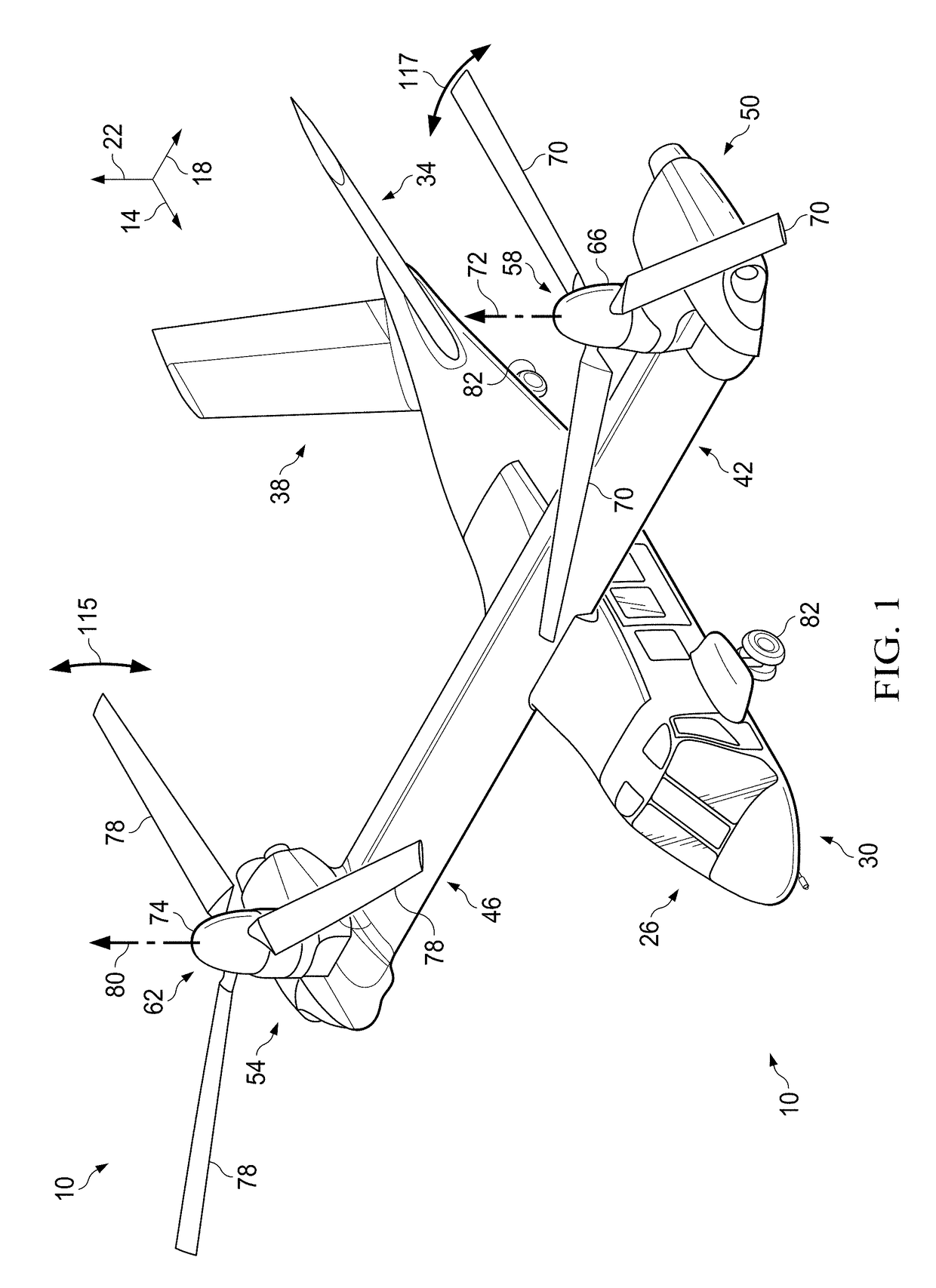
[0044]Illustrative embodiments of methods, apparatuses, and systems for customizing, manufacturing, and repairing a rotor blade using additive manufacturing processes are described below. In the interest of clarity, all features of an actual implementation may not be described in this specification. It will of course be appreciated that in the development of any such actual embodiment, numerous implementation-specific decisions must be made to achieve the developer's specific goals, such as compliance with system-related and business-related constraints, which will vary from one implementation to another. Moreover, it will be appreciated that such a development effort might be complex and time-consuming but would nevertheless be a routine undertaking for those of ordinary skill in the art having the benefit of this disclosure.

[0045]In the specification, reference may be made to the spatial relationships between various components and to the spatial orientation of various aspects of ...


PUM

PropertyMeasurementUnit
particle sizeaaaaaaaaaa
thicknessaaaaaaaaaa
thicknessaaaaaaaaaa

Abstract

In a first aspect, there is a method of making a rotor blade, including designing at least one of an upper skin, a lower skin, a support network, and components therefor; and forming at least one of the upper skin, the lower skin, a support network, and components therefor using an additive manufacturing process. In a second aspect, there is an airfoil member having a root end, a tip end, a leading edge, and a trailing edge, the airfoil member including an upper skin; a lower skin; and a support network having a plurality of interconnected support members in a lattice arrangement and/or a reticulated arrangement, the support network being configured to provide tailored characteristics of the airfoil member. Also provided are methods and systems for repairing an airfoil member.

Description

BACKGROUNDTechnical Field[0001]The present disclosure relates to an aircraft rotor blade, as well as a method of making a rotor blade.Description of Related Art[0002]Conventional aircraft rotor blades have been manufactured using a time-consuming, multi-step process involving the fabrication of several detail parts that are separately assembled to form the full rotor blade structure. Rotor blades have specific structural and dynamic requirements, which historically has driven manufacturers to separate rotor blade design and manufacture into several detail parts and sub-assemblies. Historically in the aerospace industry, the design and manufacture of multiple detail parts and sub-assemblies provides more control over the process and ensures that the assembled rotor blade meets stringent operational requirements. Oftentimes a designated set of expensive tools in a particular location is needed to manufacture each individual blade component, which can require thousands of feet in shop ...

Claims


Application Information

Patent Timeline
Patent Type & Authority Applications(United States)
IPC IPC(8): F01D5/14F01D5/00B64C11/26B33Y50/02B22F3/00B29C64/386B33Y10/00B29C73/04B22F5/04B33Y80/00B23P6/00B23K15/00B23K26/342
CPCF01D5/147B29L2031/082B64C11/26B33Y50/02B22F3/008B29C64/386B33Y10/00B29C73/04B22F5/04B33Y80/00B23P6/007B23K15/0086B23K26/342F05D2240/301F05D2230/50F05D2230/80F01D5/005B22F7/062B64C27/473F03B3/121F03D1/0675B22F2007/068B64C2027/4736F05B2230/00F05B2230/103F05B2230/30F05B2240/30F05B2250/28F05B2250/283F05B2260/84F05D2220/36B29L2031/08B29L2031/085B29L2031/087B33Y50/00B64F5/10B64F5/40G06F30/17G06F30/23Y02E10/20Y02P10/25Y02T50/60B22F10/18B22F10/25B22F10/28B22F10/12B22F10/85B22F10/47Y02P70/50
Inventor NISSEN, JEFFREYPAULSON, JARED M.CHIANG, THOMAS S.
Owner BELL HELICOPTER TEXTRON INC
Why Eureka
Try Eureka