Short-distance optical amplification module, amplification method and amplification system

a technology of optical amplification module applied in the field of short-distance optical amplification module, short-distance optical amplification method and short-distance optical amplification system, can solve the problems of difficult to meet the quality requirement of high definition and affect the quality of light reflection imaging, so as to achieve the effect of reducing the spatial distance of the three sets of components, reducing the size and volume of the short-distan

Active Publication Date: 2019-01-31
SHENZHEN DLODLO NEW TECHNOLOGY CO LTD
View PDF0 Cites 6 Cited by
  • Summary
  • Abstract
  • Description
  • Claims
  • Application Information

AI Technical Summary

Benefits of technology

[0056]Additionally, the second phase delay plate is adhered to the absorptive type polarizing plate, the imaging lens is adhered to the second phase delay plate, and the reflective type polarizing plate is adhered to the first phase delay plate, thus the spatial distance of the three sets of components may be reduced, and the size and volume of the short-distance optical amplification module may be further decreased.
[0057]The short-distance optical amplification module according to the technical solutions of the invention further comprises an optical display screen, by which the short-distance optical amplification module can realize optical imaging. When the short-distance optical amplification module is applied to virtual reality (VR) glasses, the size and volume of the VR glasses will be smaller in comparison with the existing VR glasses, and the weight will be lighter.
[0058]The short-distance optical amplification module according to the technical solutions of the invention further comprises an optical device that does not affect phase delay. The optical device brings practicability and flexibility of the optical amplification module, so that the short-distance optical amplification module according to the invention can be applicable to different optical devices and apparatuses. Additionally, the optical device may be arranged between any two adjacent components without affecting the phase delay of the optical path, and hence the practicability and flexibility of the module according to this solution may be further improved.
[0059]In the short-distance optical amplification method according to the technical solutions of the invention, by employing a short-distance optical amplification module, an optical image is reflected first and refracted finally, thus a light loss resulting from chromatic dispersion of refracted light caused by first refraction and then reflection in an existing short-distance optical amplification module may be avoided, thereby preventing the imaging quality of the light from being affected.
[0060]The solutions of the invention further provides a short-distance optical amplification system, which comprises a short-distance optical amplification module and an optical display screen, wherein, the short-distance optical amplification module is an multilayer optical module consisted of a reflective polarization layer, a first phase delay layer, an imaging lens layer, a second phase delay layer and an absorptive polarization layer, so that the size and volume of the optical module may be reduced to the maximum extent without affecting the optical imaging quality, the weight may be reduced, and the comfortableness of wearing VR glasses employing the optical amplification system is improved.
[0061]Another short-distance optical amplification system according to the technical solutions of the invention further comprises an optical device that does not affect phase delay, and the position of the optical device may be arranged freely, thus the practicability of the short-distance optical amplification system may be further improved.

Problems solved by technology

As a result, chromatic dispersion will occur to the light during transmission, the dispersed light will cause light loss, and hence the quality of light reflection imaging will be affected, and it is difficult to meet the quality requirement of high definition.

Method used


Image

  • Short-distance optical amplification module, amplification method and amplification system
  • Short-distance optical amplification module, amplification method and amplification system
  • Short-distance optical amplification module, amplification method and amplification system

Examples


Embodiment Construction

[0074]For one skilled in the art to better understand the technical solutions of the invention, the technical solutions in the embodiments of the invention will be described clearly and fully below in conjunction with the drawings in the embodiments of the invention. Apparently, the embodiments described are only a part of the embodiments of the invention, rather than being the whole embodiments. All the other embodiments obtained by one of ordinary skills in the art based on the embodiments of the invention without creative work will pertain to the protection scope of the invention.

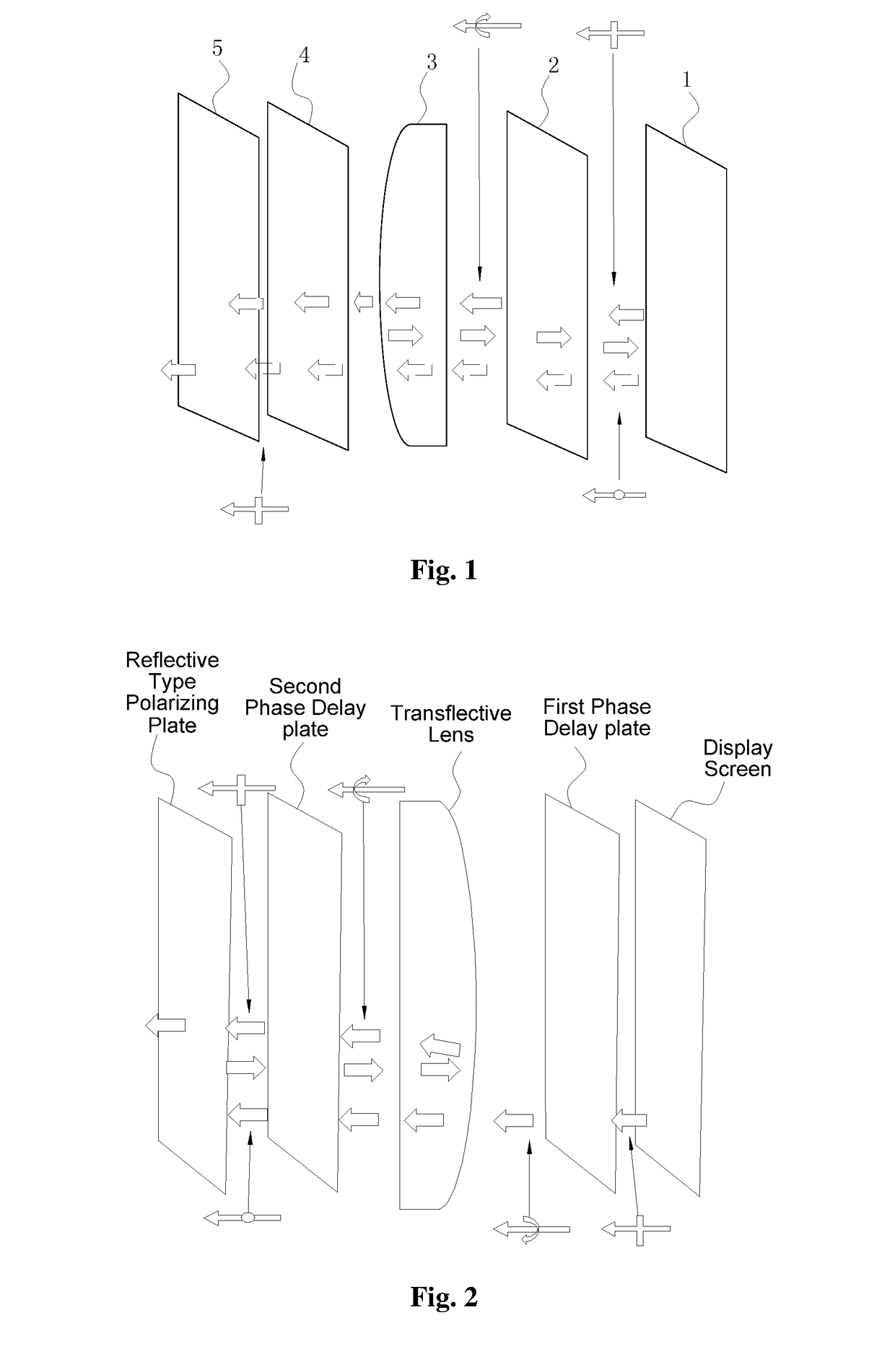
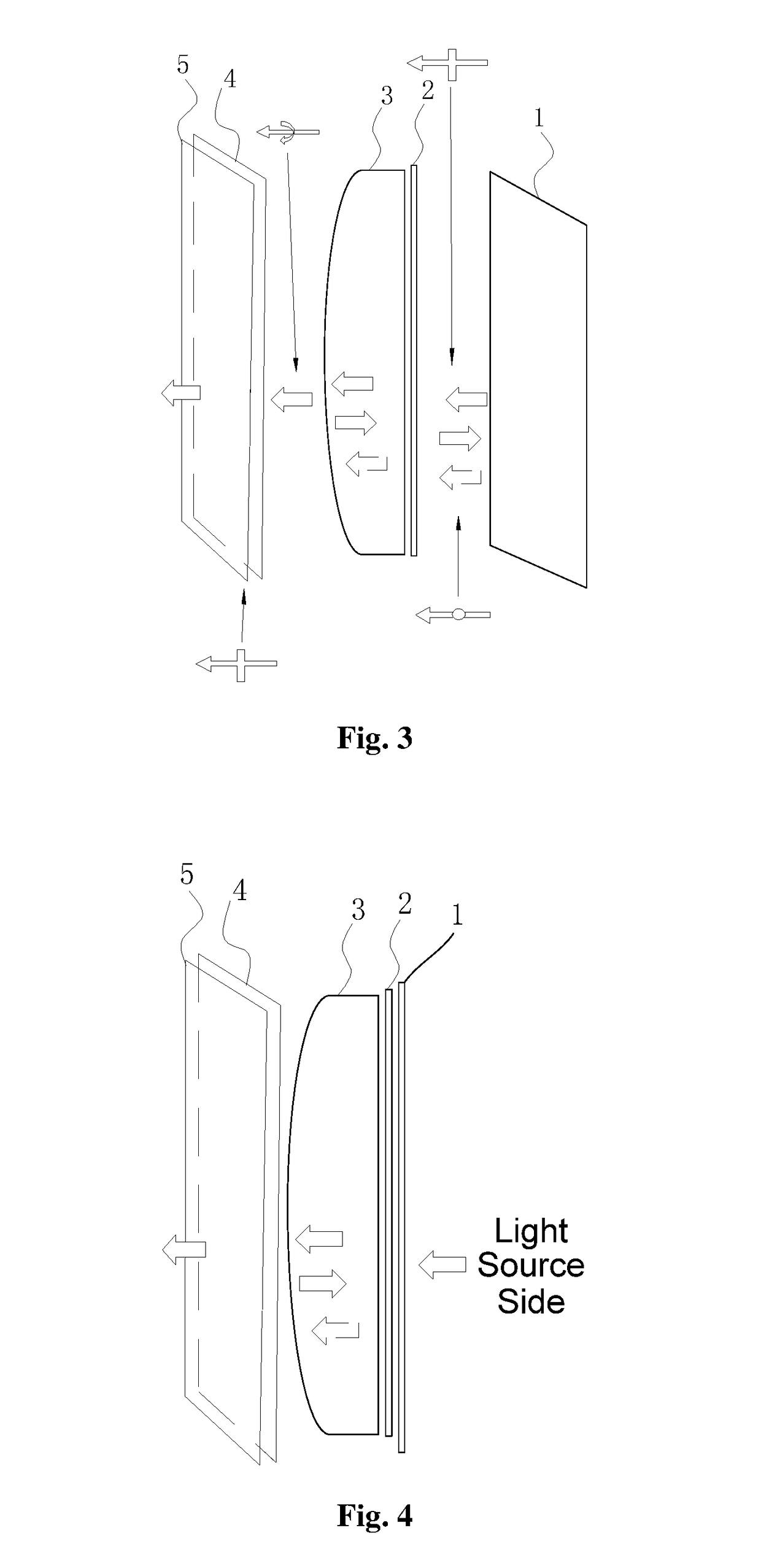
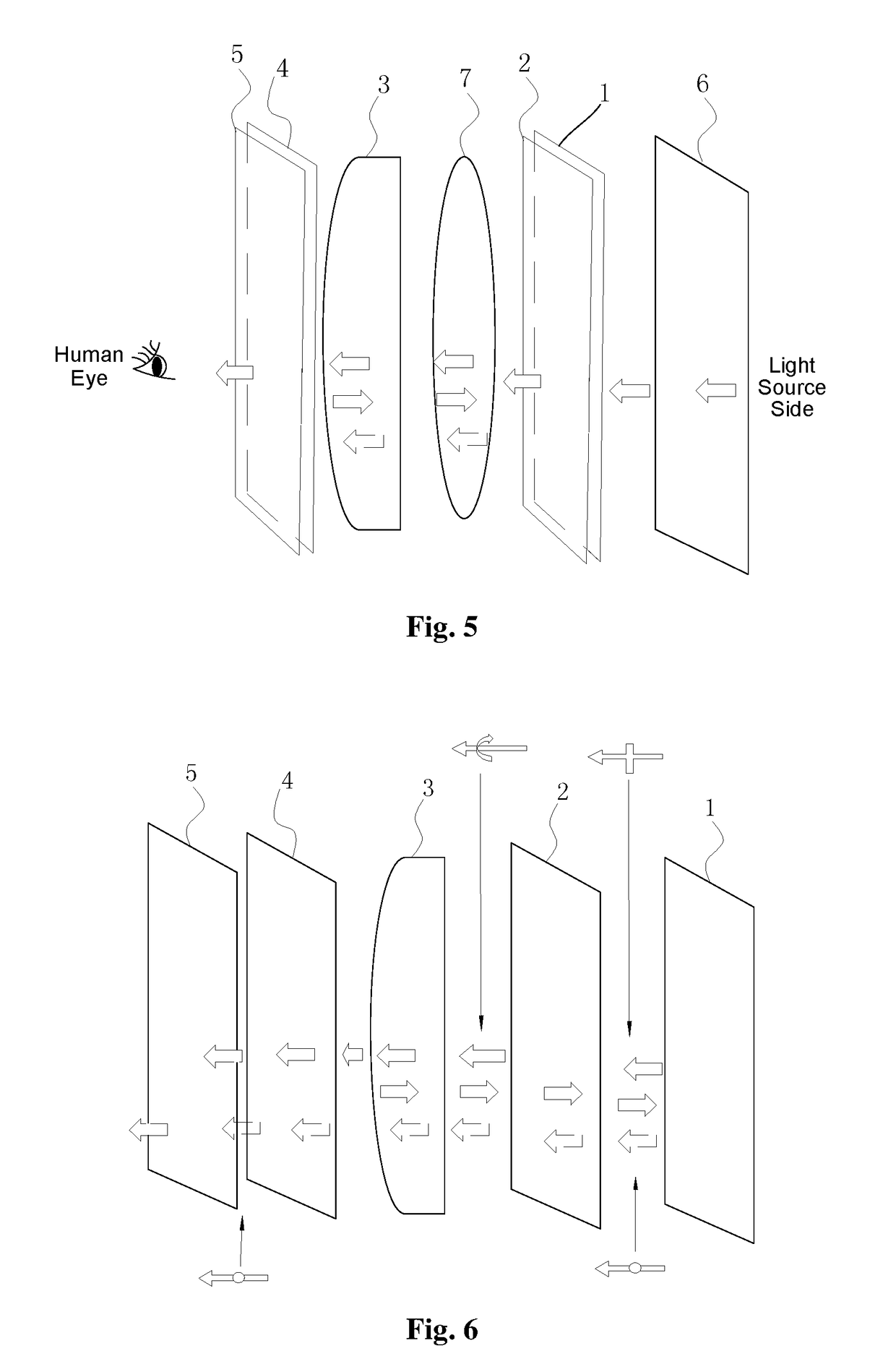
[0075]A short-distance optical amplification module, a short-distance optical amplification method and a short-distance optical amplification system will be described in detail below in conjunction with FIG. 1 to FIG. 11.

[0076]FIG. 1 is a structural representation of a short-distance optical amplification module according to an embodiment of the invention. The module includes a reflective type polarizing...


PUM


Abstract

Disclosed are a short-distance optical amplification module, method and system. The module comprises a reflective type polarizing plate, a first phase delay plate, an imaging lens, a second phase delay plate and an absorptive type polarizing plate, arranged successively. The reflective type polarizing plate is arranged on a transmission path of an optical image. The first phase delay plate is arranged on the transmission path of the optical image passing through the reflective delay plate. The imaging lens is arranged on the transmission path of the optical image. The second phase delay plate is configured for converting a polarization direction of the optical image from an elliptical or circular polarization direction to a second linear polarization direction. The absorptive type polarizing plate is arranged on one side of the second phase delay plate that faces away from the imaging lens.

Description

FIELD OF THE INVENTION[0001]The present invention relates to the field of optical module design technologies, and in particular, to a short-distance optical amplification module, a short-distance optical amplification method and a short-distance optical amplification system.BACKGROUND OF THE INVENTION[0002]The structure of an existing short-distance optical amplification module, as shown in FIG. 2, includes a display screen, a first phase delay plate, a transflective lens, a second phase delay plate and a reflective type polarizing plate. In the module, in order to amplify optical path, light is first transmitted through a transflective curved lens from one side of the first phase delay plate and then reflected by the reflective type polarizing plate. As a result, chromatic dispersion will occur to the light during transmission, the dispersed light will cause light loss, and hence the quality of light reflection imaging will be affected, and it is difficult to meet the quality requi...

Claims


Application Information

Patent Timeline
Patent Type & Authority Applications(United States)
IPC IPC(8): G02B27/00G02B27/28
CPCG02B27/0025G02B27/286G02B5/3083G02B27/0172G02B17/0856G02B25/001G02B27/28
Inventor LI, GANGTANG, WEIPING
Owner SHENZHEN DLODLO NEW TECHNOLOGY CO LTD
Why Eureka
Try Eureka