Bio-sensor

a biosensor and strip technology, applied in the field of biosensor strips, can solve the problems of pain and discomfort, pressure, friction, prior art methods of fine-tuning the shape of the socket to create a comfortable fit to the stump, laborious empirical and time-consuming, etc., to achieve the effect of reducing the number of iterations, reducing the amount of required, and improving the economic prosthesis fitting process

Pending Publication Date: 2019-02-07
ADAPTTECH LTD INST OF TRANSLATIONAL MEDICINE
View PDF3 Cites 2 Cited by
  • Summary
  • Abstract
  • Description
  • Claims
  • Application Information

AI Technical Summary

Benefits of technology

[0024]A method and apparatus according to the invention has the advantage that by mapping the bio-data onto the socket surface map, the prosthesis fitting technician is provided with an accurate guide of where issues exist at the interface between the stump and the socket, and therefore makes identification of the regions of the socket which need adapting, rectifying, tuning or shaping and the amount required thereof much easier. As a result, the number of iterations to achieve a good fit is reduced resulting in a shorter, more efficient, and more economic prosthesis fitting process. The method and apparatus of the present invention reduce the cost of fitting a new or replacement prosthetic socket, as well as for adjusting existing prosthetic sockets, and achieve comfort for the patient much more quickly.
[0025]In a particularly preferred embodiment, a plurality of temperature and pressure sensors are provided on the socket surface for collecting both temperature and pressure data relating to the engagement between the socket and the stump. The use of both temperature and pressure sensors in the stump allows an improved understanding of the engagement between the stump and the socket to be formed, the temperature sensors providing not only biometric information relating to the surface of the stump but also allows temperature compensation of the pressure readings to be carried out, thereby improving their accuracy, as well as other benefits such as obtaining information about sensitive spots which are prone to ulcers and injury.
[0026]The bio-sensors may be attached individually to the socket, it being important primarily that the exact location of each sensor in the socket, relative to a reference point, is known. Preferably, however, the bio-sensors are provided in strips or arrays, so that they may be applied to the surface of the socket in a fixed relation to each other. This has the advantage of making the application process quicker whilst at the same time ensuring accurate spacing. Furthermore, by providing the sensors in strips rather than in a web or net, the spacing between the strips can be varied to control the density of the monitoring, so that high resolution monitoring can be carried out in areas of greater interest, namely with respect to pressure or temperature variation. An appropriate pattern of sensors on or in the strip may be used, such as alternating between pressure and temperature sensors, or indeed any other bio-sensor capable of sensing and measuring a physiological or physical variable of interest.
[0027]The bio-sensors used in the present system collect bio-data from the prosthesis socket in use. The bio-sensors are thin, preferably less than 1 mm in thickness so that they themselves do not become a source of discomfort for the user and have an impact on data acquisition. Suitable models are available from Interlink Electronics Inc. of California, USA, reference FSR400. This particular model can measure applied force from 0.2N to 20 N and is particularly suited to pressure determination between the stump and the socket. In addition, these bio-sensors can measure resistances from 45 Ω to 45MΩ and vary proportionally according to the force applied over the sensing area (19.635 mm2 approximately). Other useful models include FSR400 Short from Interlink Electronics or HD-001 from IEE in Luxembourg.

Problems solved by technology

The fitting and shaping of the socket of an artificial limb (prosthesis) to ensure that the artificial limb is an accurate fit with the stump of the residual limb with which the artificial limb engages is one of the most important parts of or in the formation of a prosthesis, and also one of the most difficult.
Pain and discomfort may occur from pressure, friction, temperature, or any other physical situation caused by an improperly fitted socket or a misaligned prosthesis.
However, prior art methods of fine-tuning of the shape of the socket to create a comfortable fit to a stump are laborious, empirical and time consuming.
Such communication is, however, often imprecise and very simple, with the patient simply indicating generally where discomfort or pain is occurring on the stump.
This is made more difficult by the fact that firstly, the nature of the pain or discomfort is that the pain or discomfort usually does not just occur at the point of contact but in an area around the point of contact, so that locating the issue point precisely is very difficult.
Secondly, the patient may have to remove the stump from the socket in order to identify the pain point, and once so removed, the pain will tend to soften, again making it more difficult to accurately identify the actual contact point.
Moreover, the trauma or the pathology that led to limb loss may itself have caused nerve displacement, so that the place where pain is felt (pain point) and the actual friction or pressure spot may be in two different locations, or have caused reduced sensitivity, so that the patient is unable to give precise information.
Furthermore, the psychological trauma or indeed general reluctance of the patient to provide detailed feedback may lead to incorrect or imprecise information.
However, this approach does not provide any information on the comfort of the fit between the stump and the socket once the socket has been formed, and really only provides an alternative to taking a mould of the stump for the rough forming of the socket.
There is no teaching provided as to how to better fine tune to the fit between the stump and the socket.
Similarly, WO 2014 / 036029 discloses a viewfinder based system for acquiring data on the stump for which a prosthetics socket needs to be built, but again this does not provide any teaching regarding the fine tuning of the socket to ensure a comfortable fit.
However, this solution does not provide any teaching as to how the technician can use the collected data to improve the shape of the socket as the pressure sensors does not provide any precise spatial information which can be used to correlate the pressure data with the shape of the socket.
This is made worse by the fact that the liner is fitted to the stump, so at least the liner could only provide information on the shape of the stump rather than the socket, and in any event, due to the nature of the liner and its imprecise fitting, the exact location of the sensors on the stump cannot be ascertained in that system.
Finally, in the absence of any adhesive layer or securing mechanism, the liner cannot be prevented from continuously moving, thereby providing incorrect data.

Method used


Image

  • Bio-sensor
  • Bio-sensor
  • Bio-sensor

Examples


Embodiment Construction

[0049]The invention will now be described on the basis of the drawings. It will be understood that the embodiments and aspects of the invention described herein are only examples and do not limit the protective scope of the claims in any way. The invention is defined by the claims and their equivalents. It will be understood that features of one aspect or embodiment of the invention can be combined with a feature of a different aspect or aspects and / or embodiments of the invention.

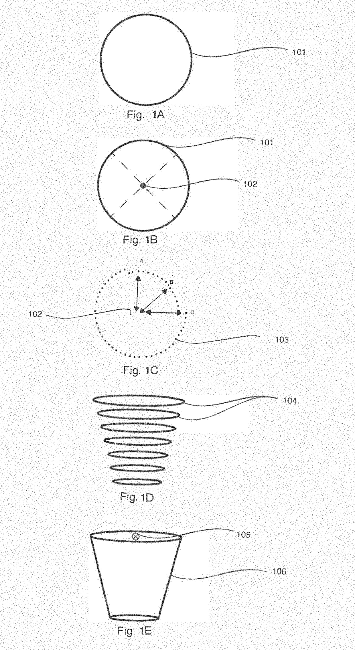
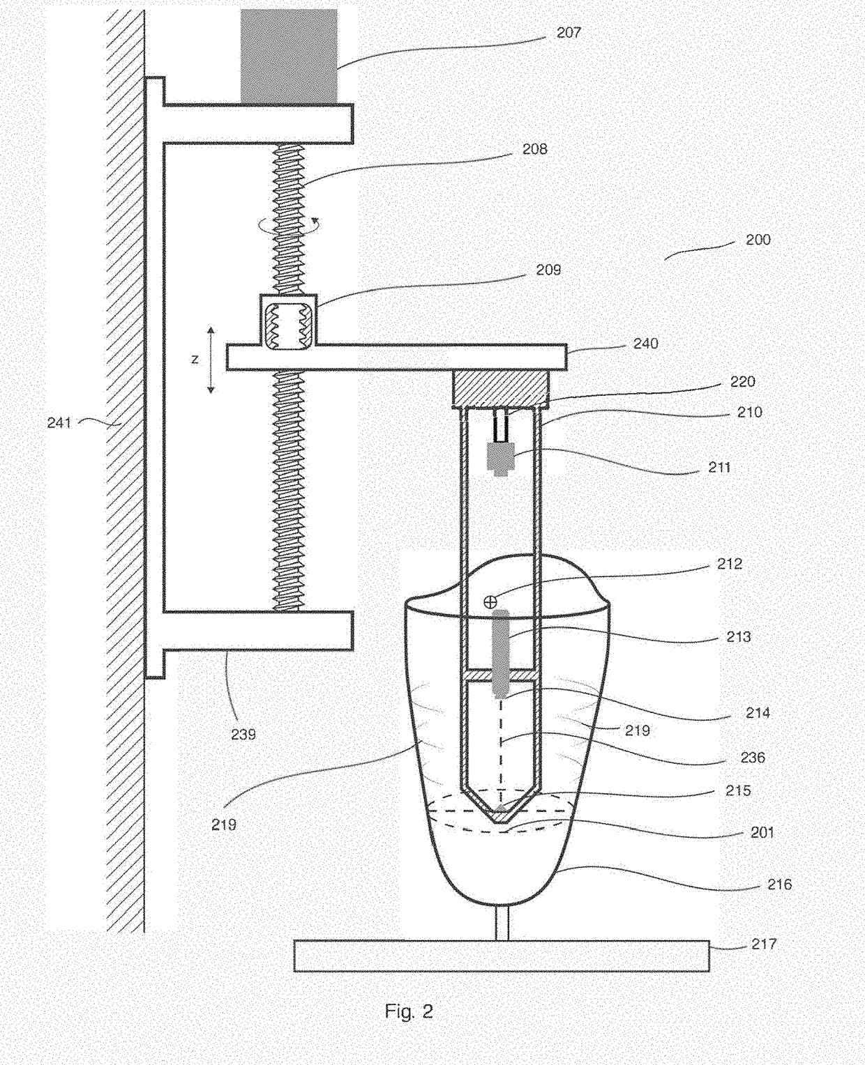
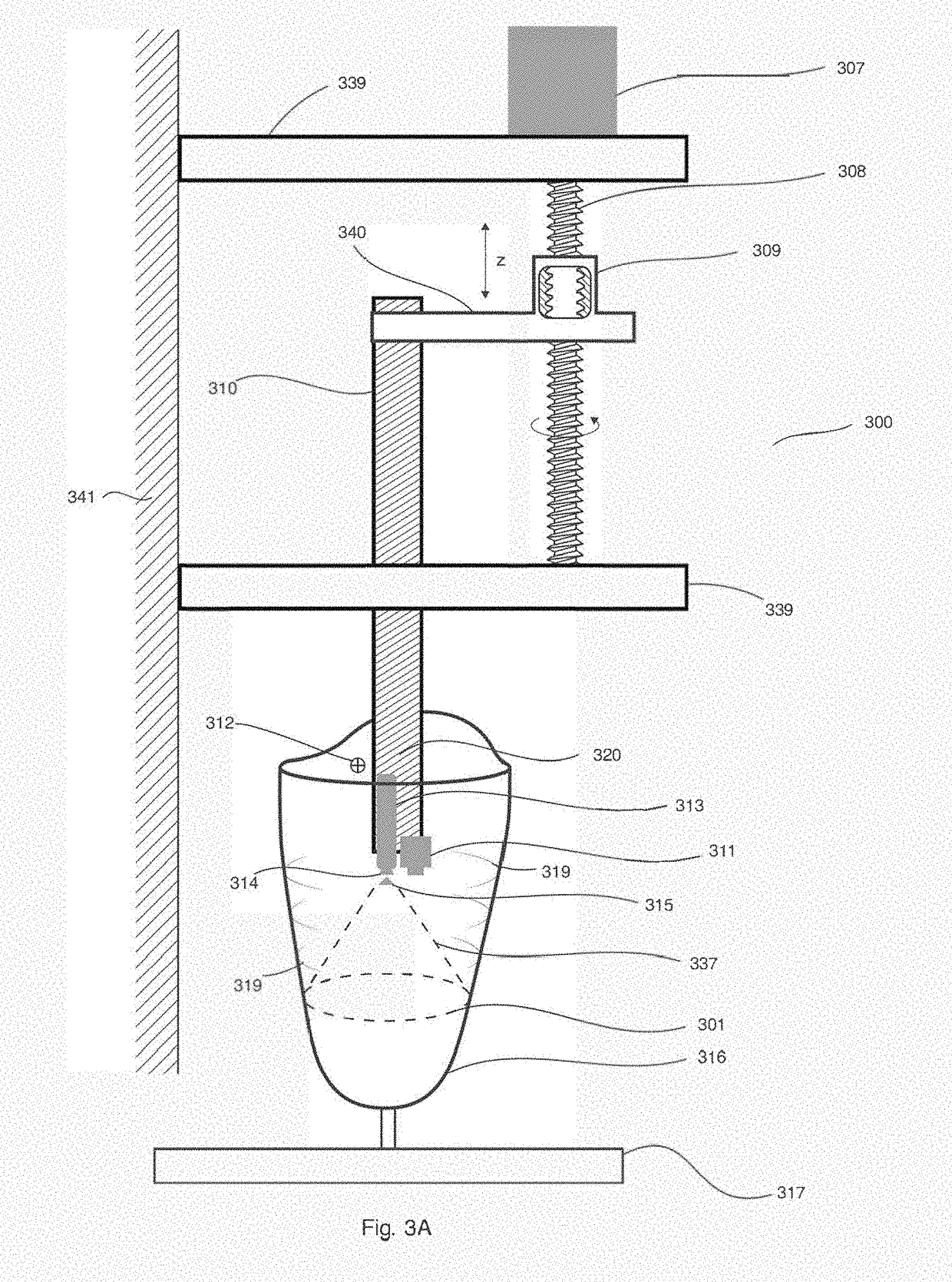
[0050]Referring first to FIGS. 1A to 1E, there is shown a summary of the steps involved in mapping and modelling in three dimensions of a socket for an artificial limb. Reference is also made to FIGS. 2 to 4 which shows the apparatus used for the mapping and modelling of the socket in three dimensions. The description below assumes that a laser is used as the radiation source, but it will be appreciated that other beams of light could be used to scan the socket of the artificial limb and this application i...


PUM


Abstract

A bio-sensor strip adapted to be located between an object and a body part. The bio-sensor strip comprises one or more of bio-sensors (819, 919) disposed on at least one first polymer film (825), wherein the bio-sensors (819, 919) measure parameters at a location between the object (216, 316, 916) and the body part (932).

Description

CROSS-REFERENCE TO RELATED APPLICATIONS[0001]This application claims priority to and benefit of Luxembourg Patent Application No. LU 100021 filed on 13 Jan. 2017.BACKGROUND OF THE INVENTIONField of the Invention[0002]The present invention relates to improvements in relations to systems, apparatus and methods of measuring and adapting objects for a comfortable engagement with an engaging member, and more particularly to a bio-sensor strip attached an object, a body part or a liner over the body part, to measure parameters between the object and the body part and thus aid in achieving a comfortable and functional fit between the object and the body part. Examples of the objects include prostheses and orthoses, for example the fitting of a prostheses to a stump of the residual limb of a wearer.Brief Description of the Related Art[0003]The fitting and shaping of the socket of an artificial limb (prosthesis) to ensure that the artificial limb is an accurate fit with the stump of the resi...

Claims


Application Information

Patent Timeline
Patent Type & Authority Applications(United States)
IPC IPC(8): A61B90/00A61F2/50A61F2/80
CPCA61B90/06A61F2/5046A61F2/80A61B2090/065A61F2002/7635A61F2002/7665A61F2/50A61B5/68335A61B5/0064A61B5/0073A61B5/0082A61B2562/0219A61B2562/0247A61B2562/0271A61B2562/029A61B2562/0295A61F2/76
Inventor ABREU CARPINTEIRO, FREDERICO ALBERTOSAENZ ESPINOZA, MARIO
Owner ADAPTTECH LTD INST OF TRANSLATIONAL MEDICINE
Why Eureka
Try Eureka