

Improvements relating to a yaw sensor for a wind turbine
- Summary
- Abstract
- Description
- Claims
- Application Information
AI Technical Summary
Benefits of technology
Problems solved by technology
Method used
Image

Examples
Embodiment Construction
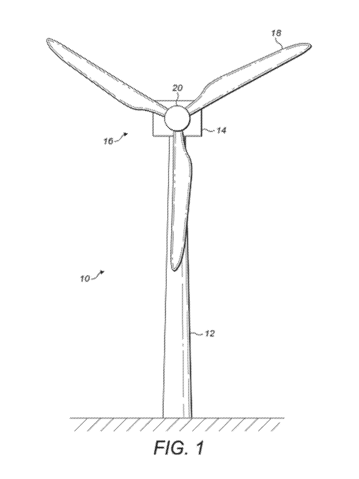
[0027]FIG. 1 shows a wind turbine 10 comprising a tower 12 supporting a nacelle 14 to which a rotor 16 is mounted. The rotor 16 comprises a plurality of wind turbine blades 18 that extend radially from a central hub 20. In this example, the rotor 16 comprises three blades 18. As discussed above, the pitch of the wind turbine blades 18 can be adjusted by a blade pitch controller (not shown), while the yaw of the nacelle 14 can be adjusted by a yaw drive (not shown) to face generally into the wind.
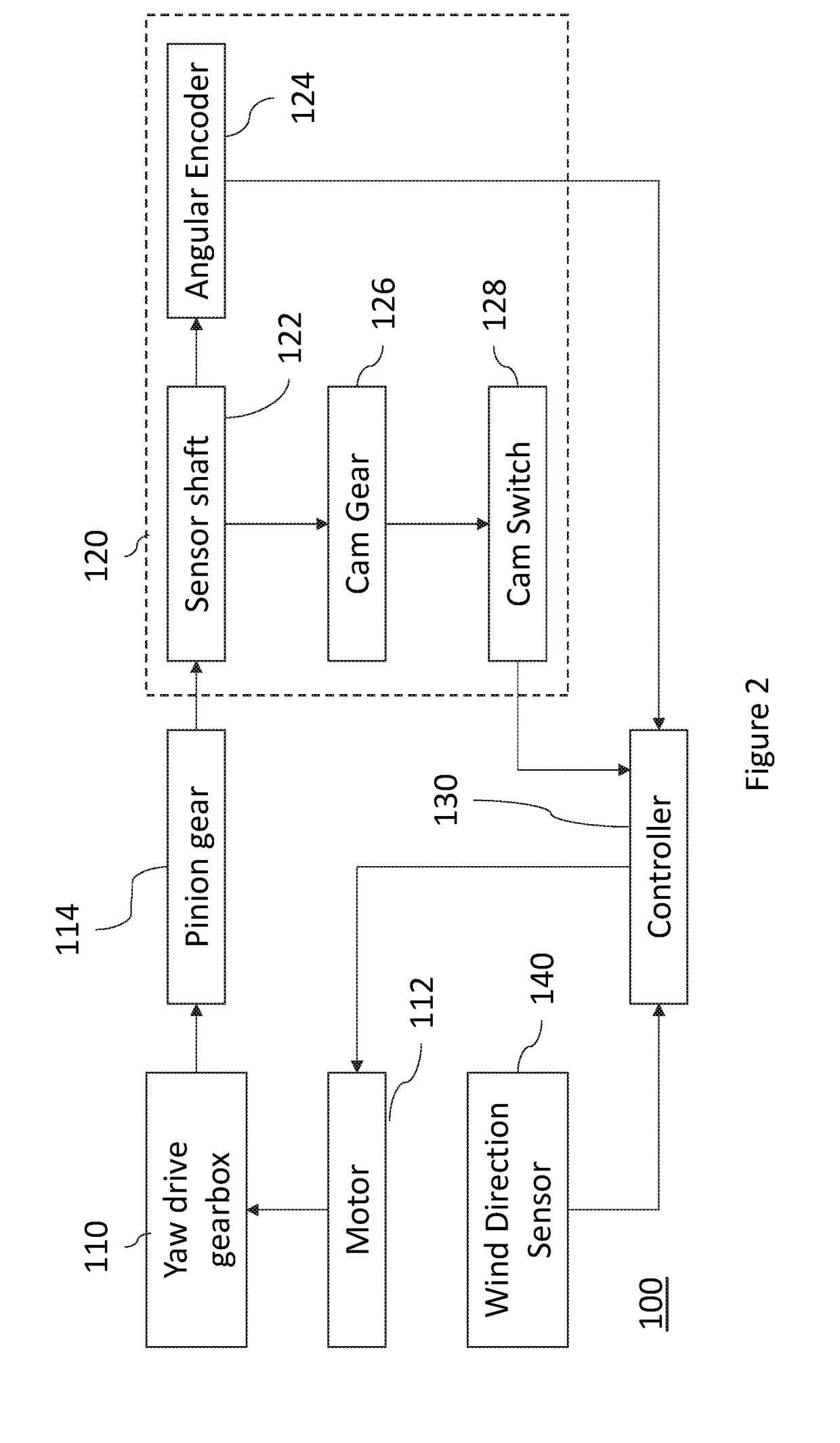
[0028]FIG. 2 shows the functional components and interrelationships of a yaw drive 100. The yaw drive 100 comprises a yaw drive gearbox 110 which is connected on the one hand to a rotating mount (not shown) on which the nacelle 14 is disposed, and on the other hand to a motor 112 which rotates a shaft for driving the rotation of the rotating mount via the gearbox 110. A yaw sensor 120 is provided, which is coupled to the yaw drive gearbox 110 (for example the yaw bearing) by way of a pinion ...
PUM
 Abstract
Description
Claims
Application Information