Electrode configuration scheme for electrophysiological testing devices

Inactive Publication Date: 2019-02-14
LIFELINES NEURO CO LLC
View PDF0 Cites 0 Cited by
  • Summary
  • Abstract
  • Description
  • Claims
  • Application Information

AI Technical Summary

Benefits of technology

[0008]One object of the present disclosure is to provide a device and system for simplified connection, disconnection, and mitigation of signal interference for an electrophysiological testing device. One or more electrophysiological electrodes and leads may be attached to the patient. The electrode leads may be bundled based on anatomical regions and may terminate at a single connector, which may be individually keyed and/or colored for ease of connection and disconnection to a junction box. Electrode bundles may be connected to a single junction box within proximity to the patient. A single ca

Problems solved by technology

By utilizing multiple cables individually attached to a BCI the mobility of a subject is limited and the ability of a medical professional to perform tests, such as MRI, is hindered at the expense of set up time.
EEG readings are highly sensitive and subject to artifacts due to movement and broken wire contacts.
Furthermore,

Method used


Image

  • Electrode configuration scheme for electrophysiological testing devices
  • Electrode configuration scheme for electrophysiological testing devices
  • Electrode configuration scheme for electrophysiological testing devices

Examples


Embodiment Construction

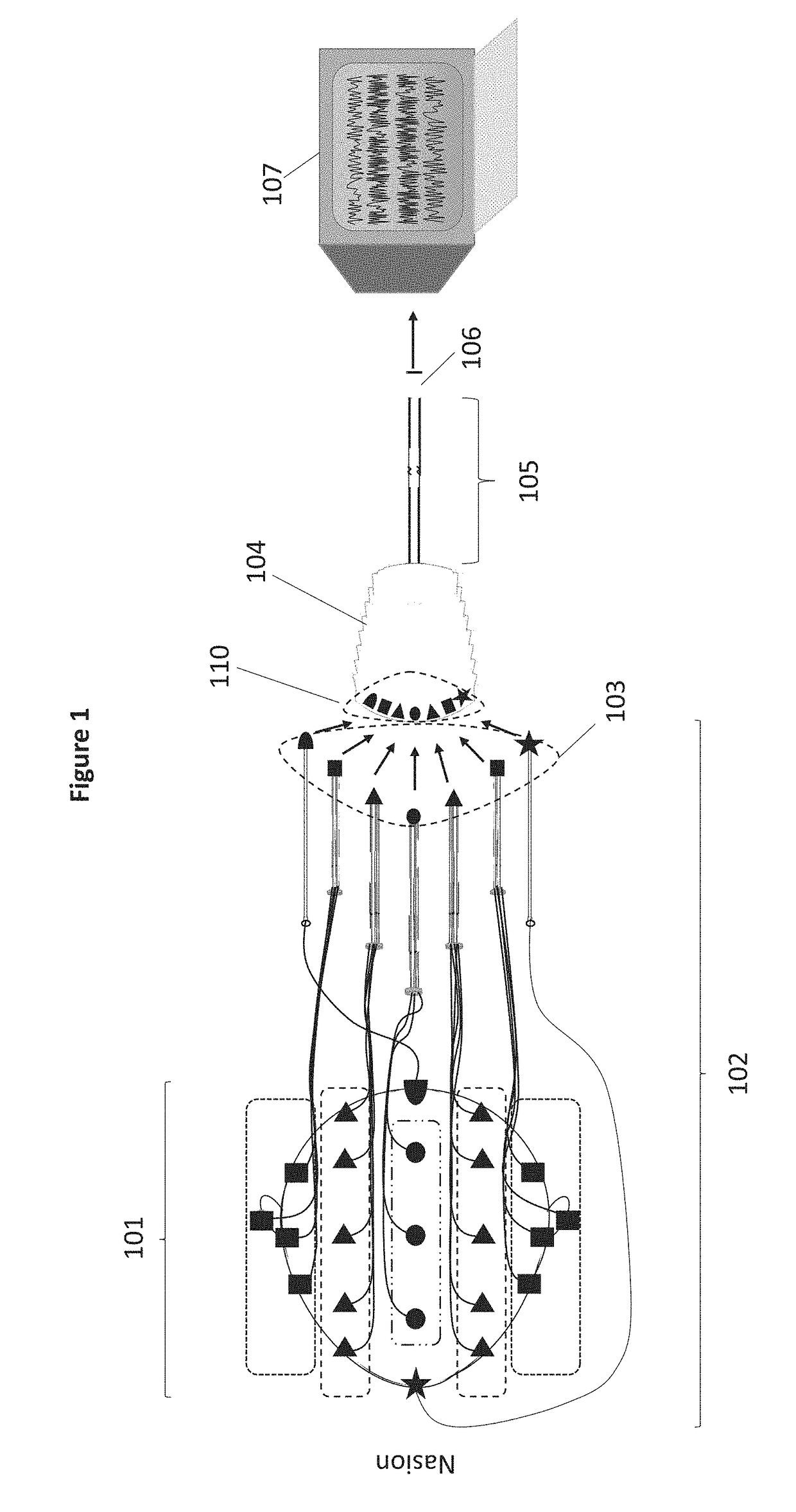
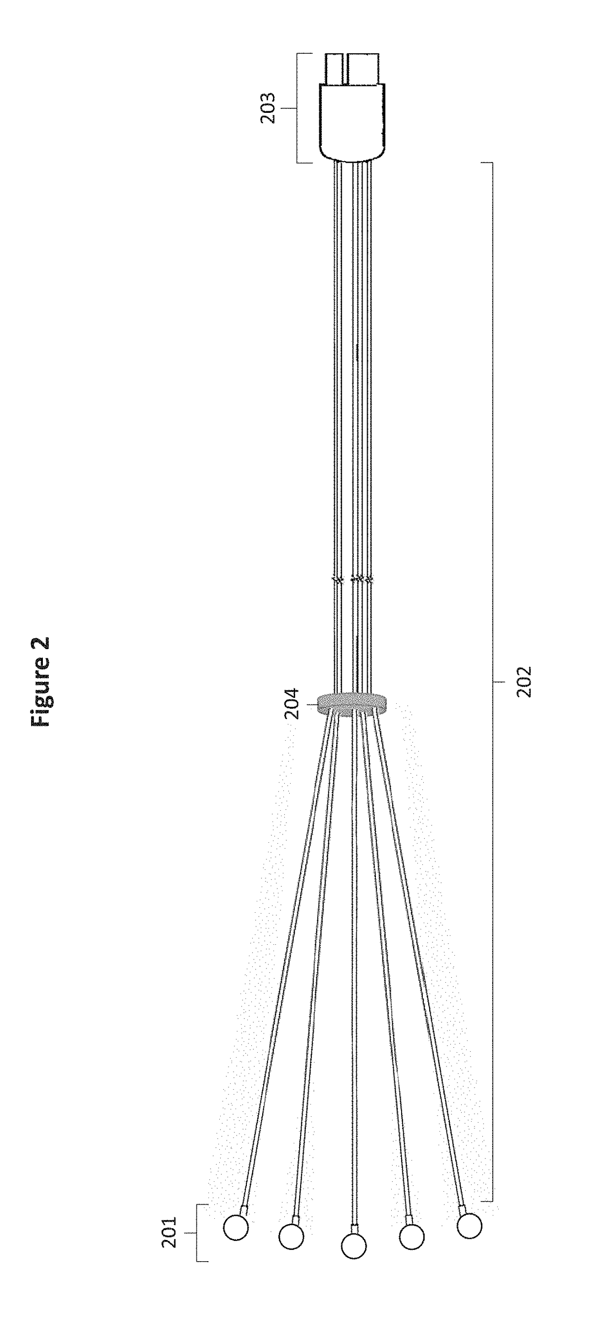
[0030]FIGS. 1-8 illustrate various embodiments of a device and system for simplifying connection and detachment of a patient to an electrophysiological testing device while maintaining test viability while connected. The embodiments provide a system which receives electrophysical signal through individual electrodes 101 attached to leads 102 which may be grouped by anatomical region and terminate at individually keyed connectors 103.

[0031]These connectors may interact with individually keyed receivers 110 of a junction box 104, with each keyed connector 103 corresponding to a particular keyed receiver 110. For example, each keyed connector 103 may correspond in shape to an individual keyed receiver 110, but not to other keyed receivers. The junction box 104 may relay individual signals through a single cable 105 and connector 106 to an electrophysiological device with user interface 107. This user interface 107 may organize and display electrophysiological data based on lead groupin...


PUM


Abstract

A device and system allows for simplified connection, disconnection, and mitigation of signal interference for electrophysiological testing. One or more electrophysiological electrodes are attached to the patient. These electrodes are connected to leads which are bundled based on region with a single connector associated with each bundle. The bundles are individually keyed and colored for ease of connection and disconnection. Leads within a bundle are organized through the use of a retainer. Electrode bundles are connected to a junction box within proximity to the patient. A single cable connects the junction box to an electrophysiological testing and monitoring interface. A system for visualizing lead bundle data, organizing individual electrode data by the lead bundles that they are associated, facilitates a workflow allowing for rapid and simple channel identification in association with specific electrode regions.

Description

[0001]This application claims priority to U.S. Provisional Patent Application Ser. No. 62 / 542,999, filed Aug. 9, 2017, the disclosure of which is incorporated herein by reference.FIELD OF INVENTION[0002]This invention is directed to electrophysiological testing, specifically, to electrode configuration and electrical connection of one or more electrophysiological testing wires between a subject and an electrophysiological device with user interface.BACKGROUND OF THE INVENTION[0003]A multitude of electrophysiological tests are currently available for medical professionals to perform on subjects in order to analyze the electrical processes of the body, including electroencephalography (EEG), electromyography (EMG), nerve conduction studies (NCS), evoked potentials (EP), electrocardiography (ECG / EKG), and Holter monitoring. Electrophysiological tests detect electrical activity transduced to the skin's surface via an electrode frequently attached by a substance such as colloidal gel or ...

Claims


Application Information

Patent Timeline
IPC IPC(8): G01N33/50B01L3/00G01N33/483
CPCG01N33/5014B01L3/5085G01N33/4836B01L2300/0645A61B2018/1467A61B5/742A61B5/24A61B5/271A61B5/369A61B5/384
Inventor EHRET, BRYANKENNEDY, DAVIDMARTIN, TYLERPOWERS, GALENUPCHURCH, STEVERYAN, OLIVIA
Owner LIFELINES NEURO CO LLC
Why Eureka
Try Eureka