
Reconfigurable Integrated-Optics-Based Non-Reciprocal Devices

Active Publication Date: 2019-02-14
RGT UNIV OF CALIFORNIA
View PDF0 Cites 2 Cited by
  • Summary
  • Abstract
  • Description
  • Claims
  • Application Information

AI Technical Summary

Benefits of technology

The present invention offers a way to reduce the cost and limitations of prior art optics devices like optical isolators and circulators. These devices can now be easily reconfigured with low-loss connections between optical ports. The reconfiguration can occur quickly, on the order of nanoseconds.

Problems solved by technology

Some photonic devices, although highly desirable, have proven difficult to include in a PIC, however.
Unfortunately, the challenges associated with their integration in PLC technology have, thus far, created barriers to their use in practical PIC systems.
Unfortunately, the utility of these devices was limited by the large footprint of an MZI structure and the bulkiness of permanent magnets.
Unfortunately, these devices were also plagued by problems such as the challenges associated with the use of an external permanent magnet or the complex fabrication to integrate strong ferromagnetic material.
Magneto-optic material, however, is characterized by a notoriously high optical insertion loss, which is exacerbated by the use of a large-footprint optical layout (e.g., an MZI).
Still further, the need for the inclusion of a permanent magnet to apply a magnetic field close to the magneto-optic waveguide creates problems in the eventual packaging of the PIC and limits the functionality of the PIC.
Previous devices are static in their functionality due to the permanent magnet and cannot be reconfigured to perform other operations.
A simple, low-loss, easily fabricated, reconfigurable non-reciprocal device suitable for integration in a PIC remains, therefore, unrealized in the prior art.

Method used


Image

  • Reconfigurable Integrated-Optics-Based Non-Reciprocal Devices
  • Reconfigurable Integrated-Optics-Based Non-Reciprocal Devices
  • Reconfigurable Integrated-Optics-Based Non-Reciprocal Devices

Examples


Embodiment Construction

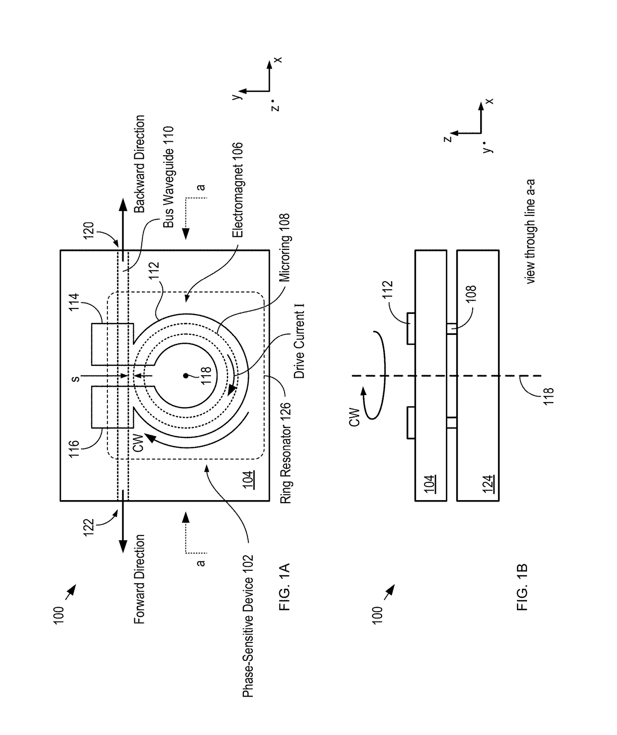
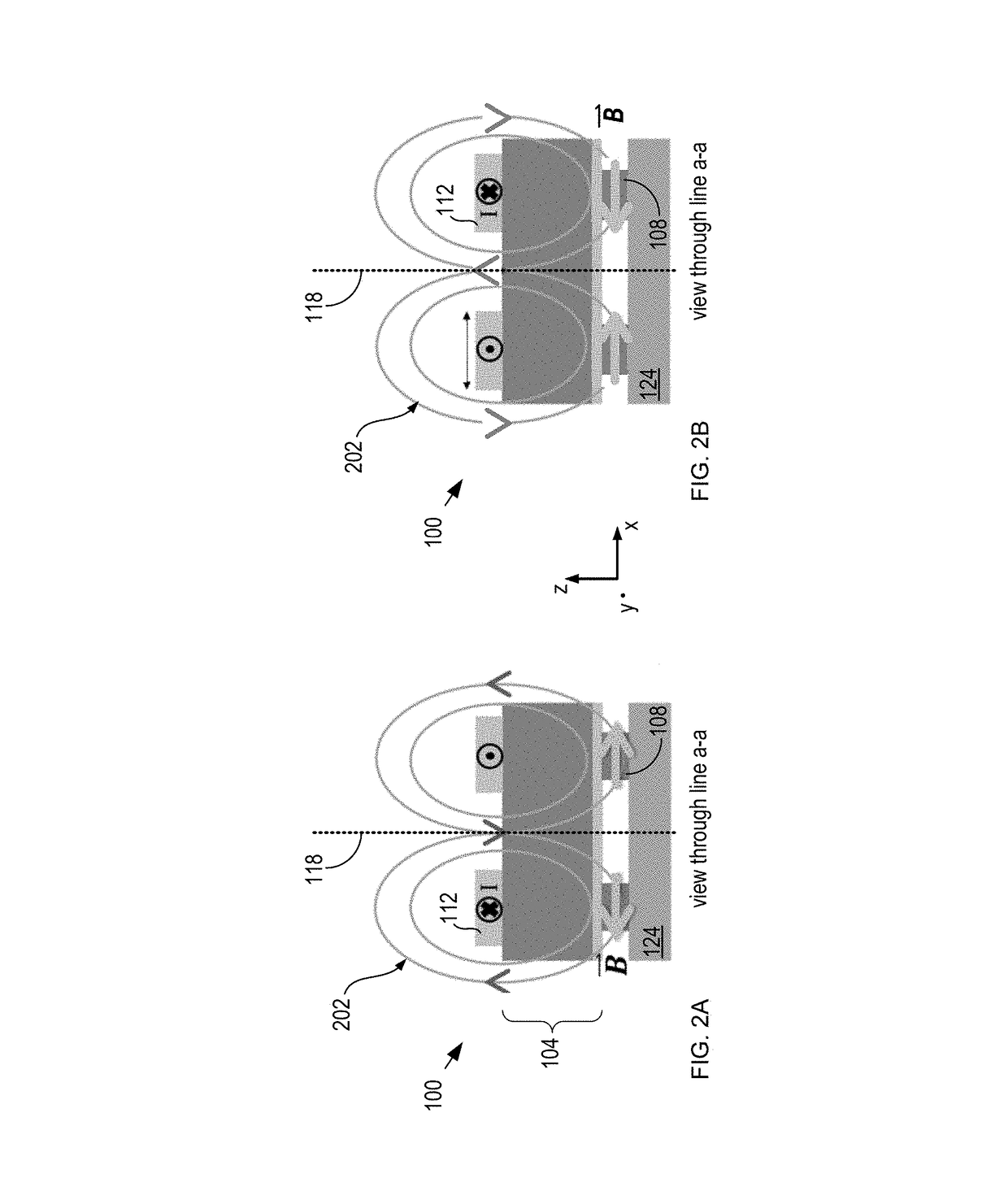
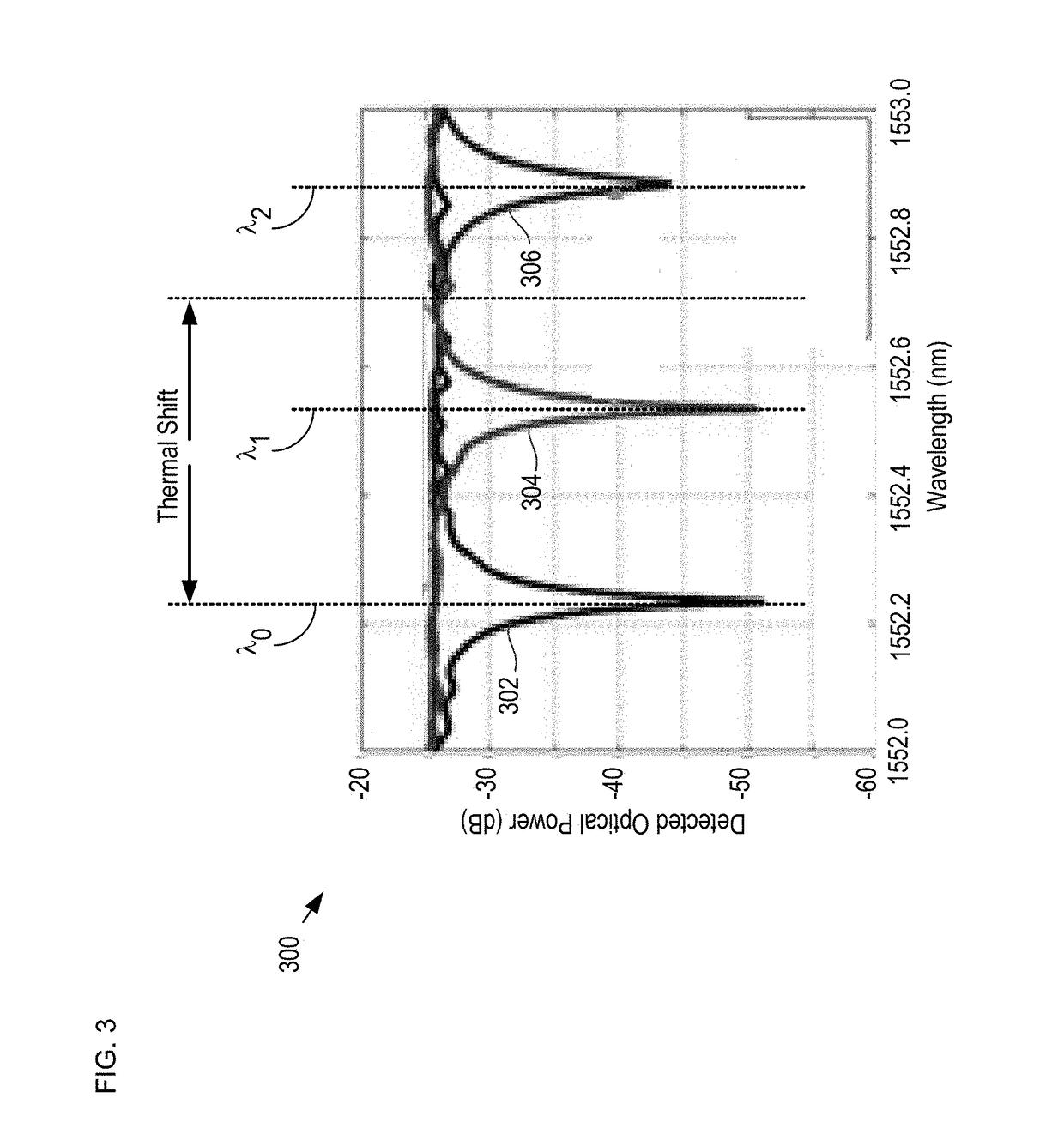
[0040]The present invention exploits the fact that a non-reciprocal phase shift can be induced in an integrated-optics-based phase-sensitive device, such as a ring resonator or Mach-Zehnder interferometer, by coupling the device with a magneto-optic layer and applying a magnetic field to the resultant structure. As disclosed in U.S. Pat. No. 8,396,337, which is incorporated herein by reference, the magnetic field can be generated via an electromagnet formed on top of the magneto-optic layer, which overcomes many of the problems associated with permanent-magnet-based non-reciprocal devices. In addition, since the magnitude of the drive current in an electromagnet can be controlled, the strength of the magnetic field can be tailored to achieve the desired amount of nonreciprocal phase shift (NRPS). In a resonant, ring-resonator based device, this effect produces a desired magnitude of the resonance wavelength split (RWS) induced in the device and, therefore, the CW and CCW resonance w...


PUM


Abstract

Reconfigurable non-reciprocal integrated-optics-based devices are disclosed. The non-reciprocal devices include: a phase-sensitive device, such as a microring waveguide; a magneto-optic layer; and an electromagnet. These elements are operatively coupled such that a magnetic field generated by current flow through the electromagnet gives rise to a non-reciprocal phase shift in the phase-sensitive device. The non-reciprocal phase shift leads to a difference in the way that a light signal travels in the forward and backward directions through one or more bus waveguides that are operatively coupled with the phase-sensitive element. The non-reciprocity is reversible by reversing the direction of drive current flow in the electromagnet, which enables the inter-port connectivity of the ports of these bus waveguides to be reconfigured based on the direction of the drive current flow. Examples of reconfigurable isolator and circulator embodiments are described.

Description

RELATED APPLICATIONS[0001]This application claims the benefit of U.S. Provisional Application No. 62 / 290,341 filed Feb. 2, 2016 (Attorney Docket: 331-013PR1). The entire disclosure of U.S. Provisional Application No. 62 / 290,341 is incorporated herein by reference.FIELD OF THE INVENTION[0002]The present invention relates to integrated-optics technology in general, and, more particularly, to magneto-optically actuated integrated-optics-based switching devices.BACKGROUND OF THE INVENTION[0003]A photonic integrated circuit (PIC) is an optical system that is integrated on a substrate, where the optical system includes a plurality of photonic functions, such as light generation, transmission, filtering, modulation, switching, detection and the like. PICs are analogous to electronic integrated circuits; however, a PIC operates primarily in the optical domain. A typical PIC includes one or more photonic devices, such as light sources, optical modulators, detectors, etc., which are integrate...

Claims


Application Information

Patent Timeline
IPC IPC(8): G02F1/09G02F1/095G02B6/27G02B6/42
CPCG02F1/092G02F1/0955G02B6/2746G02B6/4209G02F1/313G02F2/002
Inventor BOWERS, JOHN E.PINTUS, PAOLOHUANG, DUANNI
Owner RGT UNIV OF CALIFORNIA
Learn More