Pedal Assembly With Debris Filtering Mechanism

a technology of debris filtering and pedal assembly, which is applied in the direction of mechanical control devices, instruments, process and machine control, etc., can solve the problems of reducing the life and inconsistent operation of the pedal assembly during subsequent use, cumbersome removal of contaminants, and sometimes submerged pedal assembly, etc., to reduce the cost and complexity of manufacturing, and improve the effect of functionality and usability

Active Publication Date: 2019-02-14
KONGSBERG POWER PROD SYST I
View PDF9 Cites 3 Cited by
  • Summary
  • Abstract
  • Description
  • Claims
  • Application Information

AI Technical Summary

Benefits of technology

[0006]The present invention overcomes the disadvantages in the prior art in a pedal assembly for a vehicle. The pedal assembly includes a pedal arm moveable between a first position and a second position. A pivot shaft is operatively attached to the pedal arm. The pivot shaft defines a pivot axis. A housing having a mount adapted for attachment to the vehicle is provided. The housing defines a bore supporting at least a portion of the pivot shaft to permit rotation of the pedal arm about the pivot axis. A debris filtering mechanism is formed in at least one of the pivot shaft and the bore to direct contaminants away from the pedal assembly and out of the bore as the pedal arm moves between the first position and the second position.
[0007]In this way, the pedal assembly of the present invention provides improved functionality and usability in connection with vehicles and, at the same time, reduces the cost and complexity of manufacturing and assembling pedal assemblies which can operate reliably and predictably in a number of different environments.

Problems solved by technology

In these industries, the pedal assembly may occasionally be submerged in or otherwise exposed to a coarse slurry of water and mud / sand, or other contaminants.
In such circumstances, the accumulation or presence of contaminants may be detrimental to proper operation of the pedal assembly, and frequently exacerbates wear of certain components of the pedal assembly, resulting in reduced life and inconsistent operation during subsequent use.
Moreover, proper removal of contaminants may be cumbersome.
However, these types of pedal assemblies tend to be relatively cumbersome and expensive to manufacture, and may be relatively heavy and require a large packaging size.

Method used


Image

  • Pedal Assembly With Debris Filtering Mechanism
  • Pedal Assembly With Debris Filtering Mechanism
  • Pedal Assembly With Debris Filtering Mechanism

Examples


Embodiment Construction

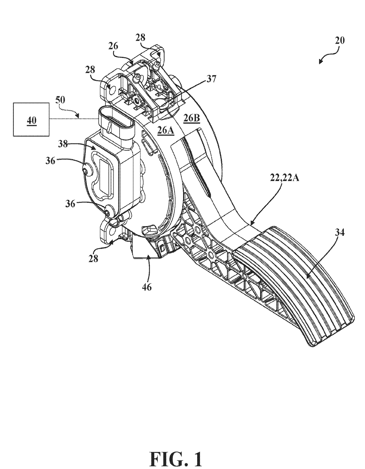
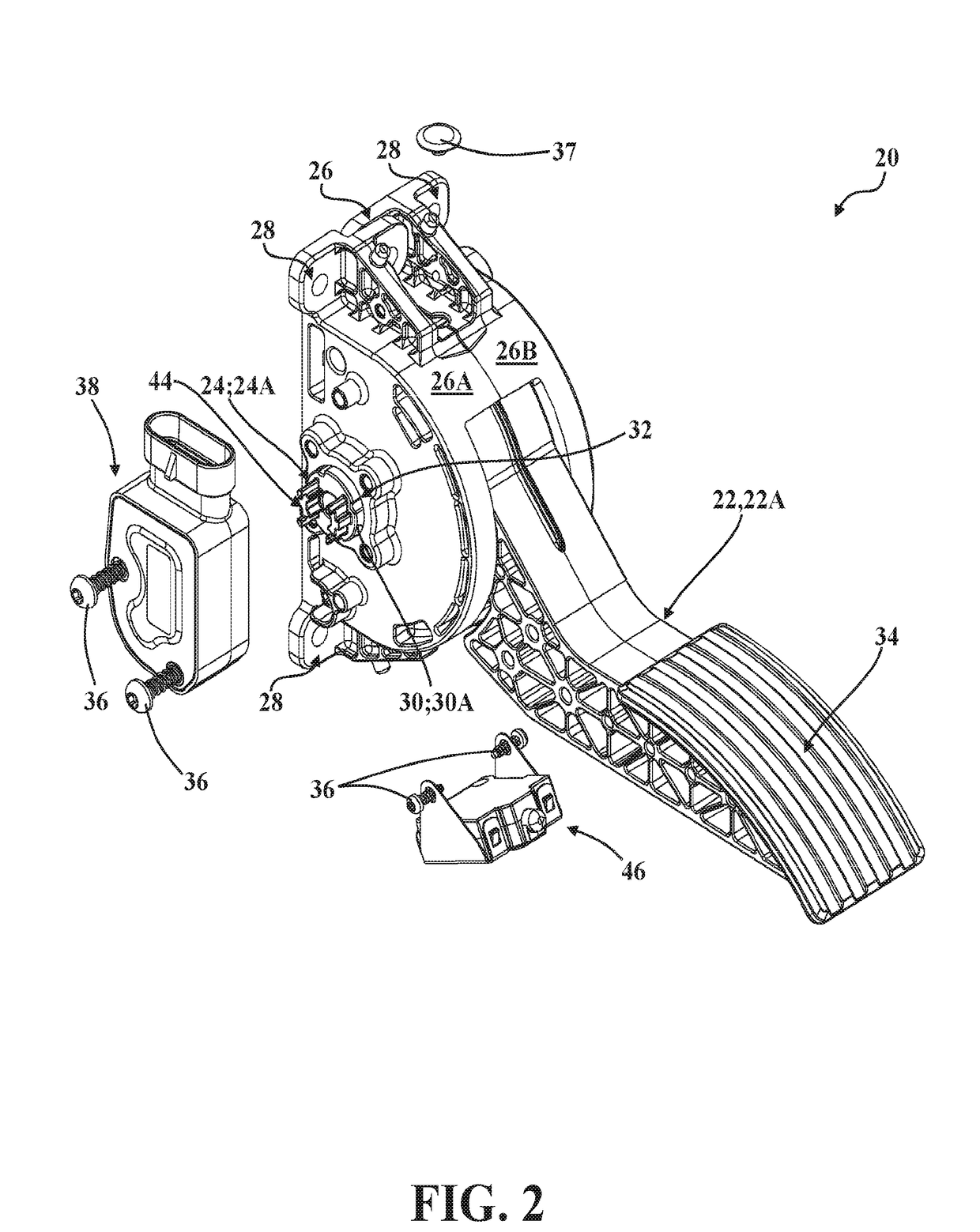
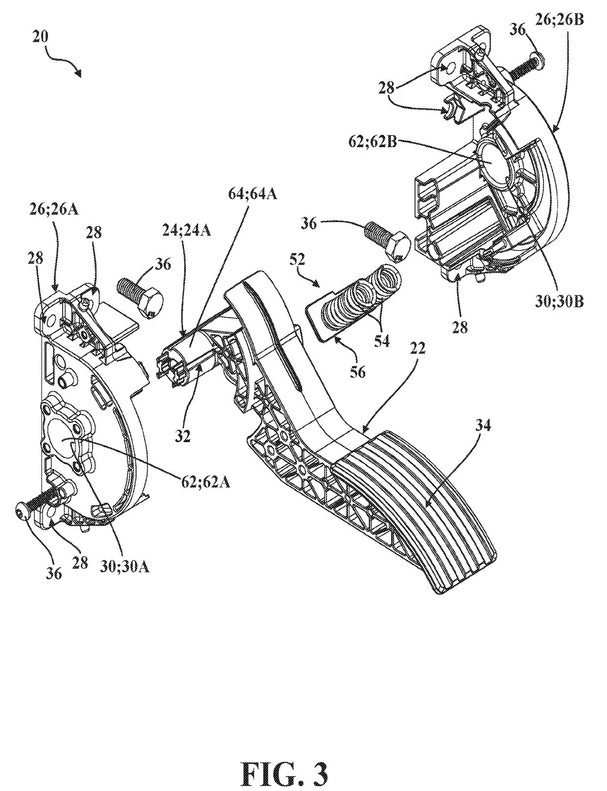
[0024]Referring now to the drawings, where like numerals indicate like or corresponding parts throughout the several views, a pedal assembly is generally shown at 20 in FIGS. 1-3. The pedal assembly 20 is adapted for use in a vehicle (not shown, but generally known in the art) and allows a driver to selectively actuate the pedal assembly 20 so as to control the vehicle in operation, as described in greater detail below. To that end, the pedal assembly 20 could be realized as an “accelerator pedal” used to control vehicle acceleration and modulate vehicle speed, a “brake pedal” used to decelerate and stop the vehicle, a “clutch pedal” used to modulate translation of rotational torque between an engine and a transmission, and the like. Moreover, as will be appreciated from the subsequent description below, the pedal assembly 20 could be used to control the vehicle in any suitable way without departing from the scope of the present invention. While the pedal assembly 20 may advantageou...


PUM


Abstract

A pedal assembly for a vehicle, including a pedal arm moveable between a first position and a second position, and a pivot shaft is operatively attached to the pedal arm. The pivot shaft defines a pivot axis. A housing having a mount adapted for attachment to the vehicle is provided. The housing defines a bore supporting at least a portion of the pivot shaft to permit rotation of the pedal arm about the pivot axis. A debris filtering mechanism is formed in at least one of the pivot shaft and the bore to direct contaminants away from the pedal assembly and out of the bore as the pedal arm moves between the first position and the second position.

Description

CROSS-REFERENCE TO RELATED APPLICATION[0001]The subject patent application claims priority to and all the benefits of U.S. Provisional Patent Application Ser. No. 62 / 220,507, which was filed on Sep. 18, 2015, the disclosure of which is hereby incorporated by reference.BACKGROUND OF THE INVENTION1. Field of the Invention[0002]The present invention relates, generally, to pedal assemblies for vehicles and, more specifically, to a pedal assembly with a debris filtering mechanism.2. Description of the Related Art[0003]Conventional pedal assemblies known in the art are employed to allow a driver to selectively control operation of a vehicle. To that end, pedal assemblies may be realized as an “accelerator pedal” used to control vehicle acceleration and modulate vehicle speed, a “brake pedal” used to control vehicle deceleration and stop the vehicle, or a “clutch pedal” used to modulate translation of rotational torque between an engine and a transmission.[0004]It will be appreciated that ...

Claims


Application Information

Patent Timeline
Patent Type & Authority Applications(United States)
IPC IPC(8): G05G25/04G05G1/38G05G1/44G05G5/05
CPCG05G25/04G05G1/38G05G1/44G05G5/05B60T7/06B60K26/02B60K20/04F16C2360/00F16C11/045G05G1/445
Inventor HENRIKSON, JESSE
Owner KONGSBERG POWER PROD SYST I
Why Eureka
Try Eureka