
Method for manufacturing array substrate and array substrate

a technology which is applied in the field of array substrate and manufacturing method of array substrate, can solve the problems of reducing the yield of products and increasing production costs, and achieve the effects of improving product yield, saving costs, and simplifying manufacturing processes

Active Publication Date: 2019-02-14
WUHAN CHINA STAR OPTOELECTRONICS TECH CO LTD
View PDF0 Cites 1 Cited by
  • Summary
  • Abstract
  • Description
  • Claims
  • Application Information

AI Technical Summary

Benefits of technology

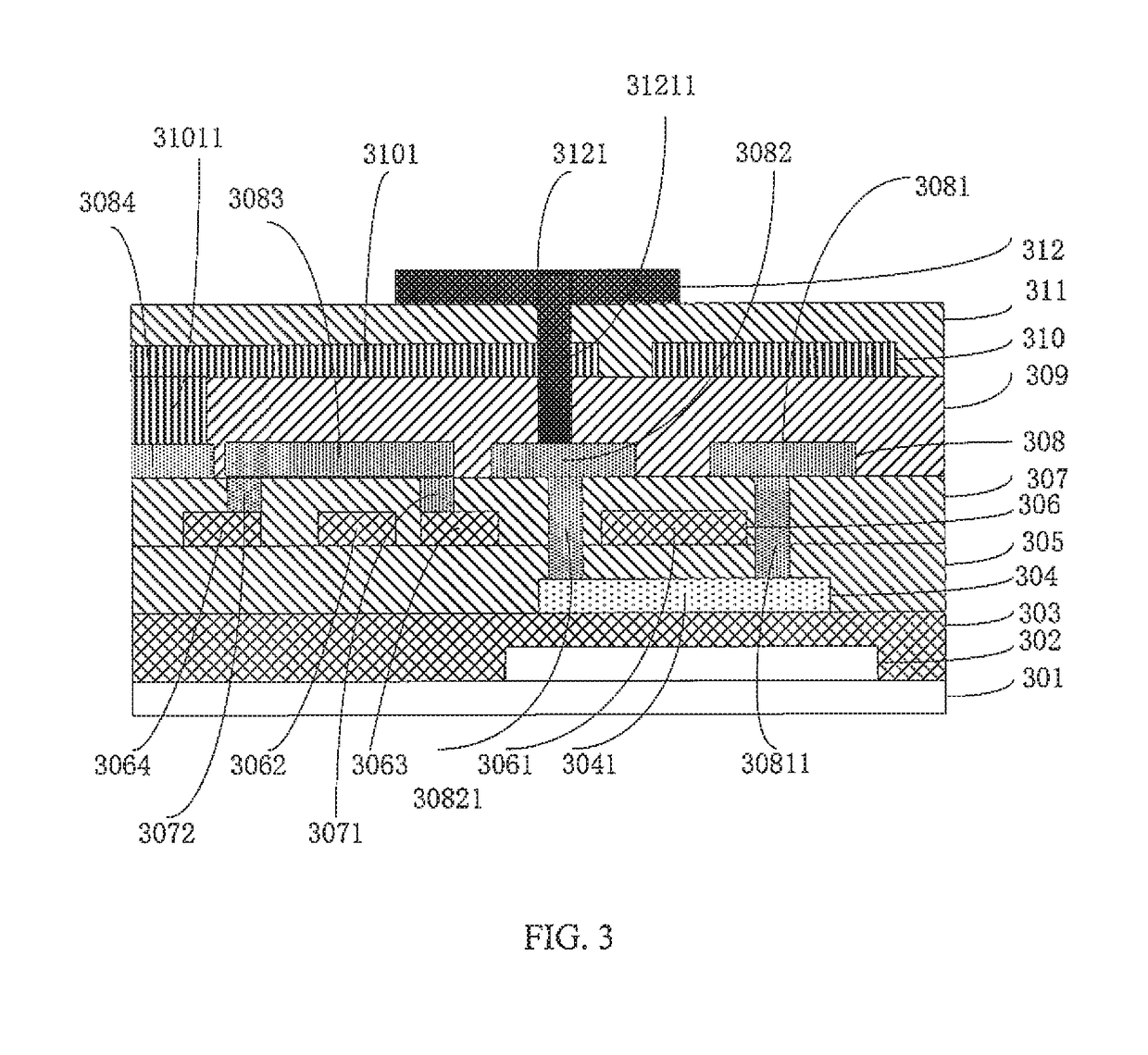
The present invention provides a method and substrate for manufacturing an array substrate that simplifies the process, saves money, and improves yield and market competitiveness. Specifically, the method involves placing a first metal layer on an insulating layer to form the gate, scan line, and data lines, and a second metal layer on an insulating layer to form the source, drain, connecting line, and touch signal line of the thin film transistor. The connecting line connects the first and second data lines, further simplifying the process.

Problems solved by technology

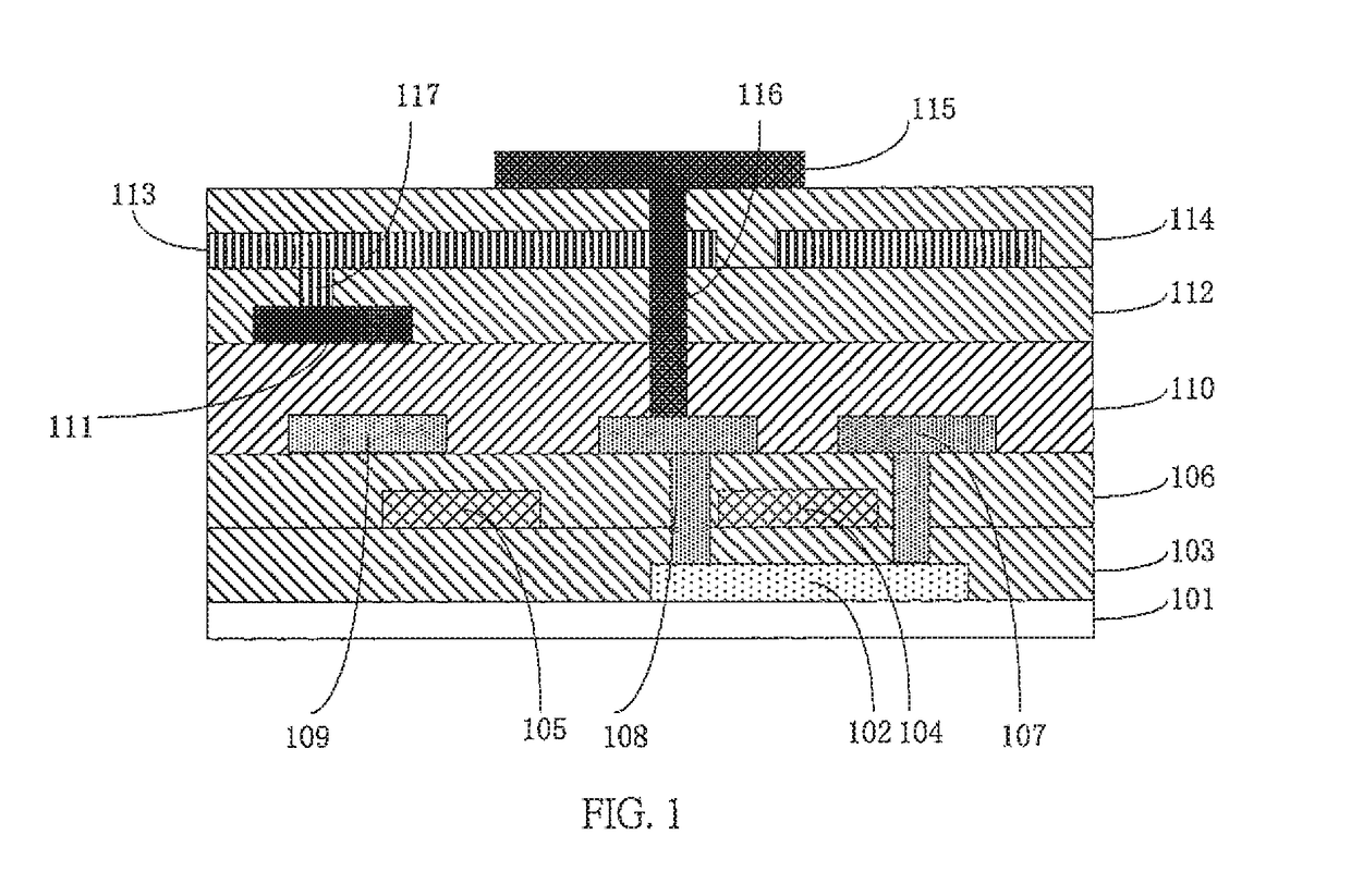
Thus, in order to dispose the touch signal line 111, in the manufacturing process of the array substrate, a metal manufacturing process and the third metal layer are added, increasing the cost of production and reducing the yield of the products.

Method used


Image

  • Method for manufacturing array substrate and array substrate
  • Method for manufacturing array substrate and array substrate
  • Method for manufacturing array substrate and array substrate

Examples


Embodiment Construction

[0065]The technical means and the effects thereof will be described in further detail with reference to the preferred embodiments of the present disclosure and the accompanying drawings thereof. Obviously, the described embodiments are merely part of the present disclosure, rather than all embodiments. Based on embodiments in the present invention, all other embodiments obtained by a person of ordinary skill in the art without making creative work are within the scope of the present disclosure.

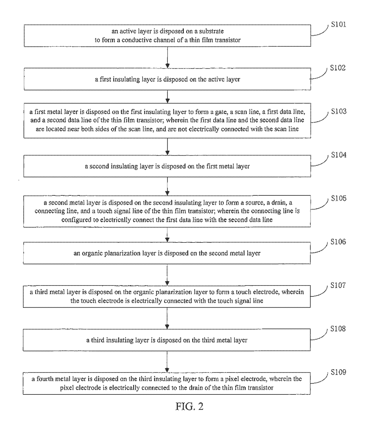
[0066]Refer to FIG. 2, which is a schematic flow chart of the steps of the method for manufacturing an array substrate in accordance with a preferred embodiment of the present disclosure. As shown in FIG. 2, the method of manufacturing the array substrate in accordance with the present preferred embodiment includes the following steps:

[0067]In step S101, an active layer is disposed on a substrate to form a conductive channel of a thin film transistor.

[0068]In step S102, a first insulating laye...


PUM


Abstract

A method for manufacturing an array substrate and an array substrate are provided, which include a first insulating for forming a gate, a scan line, a first data line, and a second data line of the thin film transistor, wherein the first data line and the second data line are located near both sides of the scan line, and are not electrically connected with the scan line, and a second insulating layer for forming a source, a drain, a connecting line, and a touch signal line of the thin film transistor, wherein the connecting line is configured to electrically connect the first data line with the second data line.

Description

FIELD OF THE INVENTION[0001]The present disclosure relates to the technical field of displays, and particularly to an array substrate and a method for manufacturing an array substrate.BACKGROUND OF THE INVENTION[0002]Common electrodes in the effective display region are divided into small blocks as touch electrodes in the incell touch technique. Each of the touch electrodes has a touch signal line electrically connected with a touch chip for receiving touch signals.[0003]Refer to FIG. 1, which is a structural schematic diagram of an existing array substrate. As shown in FIG. 1, in the manufacturing process of the existing array substrate, the active layer is disposed on a substrate 101 to form a conductive channel 102 of a thin film transistor. A first insulating layer 103 and the first metal layer are successively disposed on the active layer to form a gate 104 and a scan line 105 of the thin film transistor. The second insulating layer 106 is disposed on the first metal layer, fol...

Claims


Application Information

Patent Timeline
IPC IPC(8): G06F3/047H01L27/12G06F3/041
CPCH01L27/1262H01L27/124H01L27/1259H01L29/78633G02F1/13
Inventor HONG, GUANGHUIGONG, QIANG
Owner WUHAN CHINA STAR OPTOELECTRONICS TECH CO LTD
Learn More