Wideband gysel power divider

Active Publication Date: 2019-02-14
TTM TECH INC
View PDF0 Cites 6 Cited by
  • Summary
  • Abstract
  • Description
  • Claims
  • Application Information

AI Technical Summary

Benefits of technology

[0006]The present invention provides a modified Gysel power divider in a compact multilayer surface mount component that can perform power division/combining with low insertion loss, wide bandwidth, design flexibility and high power handling capabilities. In one embodiment, the power divider comprises a first port, a first pair of coupled transmission lines interconnected to the first port, a second port coupled to one of the first pair of coupled transmission lines, a third port coupled to the other of the first pair of coupled transmission lines, a second pair of coupled transmission lines interconnected by a long transmission line, wherein each of the pair of coupled transmission lines is connected to a grounded isolation resistor that can be external or i

Problems solved by technology

An isolation resistor of value 2 Zo is added between the output ports, which imposes limitations for frequency operation, power handling and size.
The main disadvantage of this approach is that it is incapable of achieving high bandwidth with higher isolation.
However, this solution is larger, adds insertion loss, and requires more isolation resistors, which can be difficult to get in the market for broadband operation.
Moreover, the Wilkinson power divider is not the best choice when high power is require

Method used


Image

  • Wideband gysel power divider
  • Wideband gysel power divider
  • Wideband gysel power divider

Examples


Example

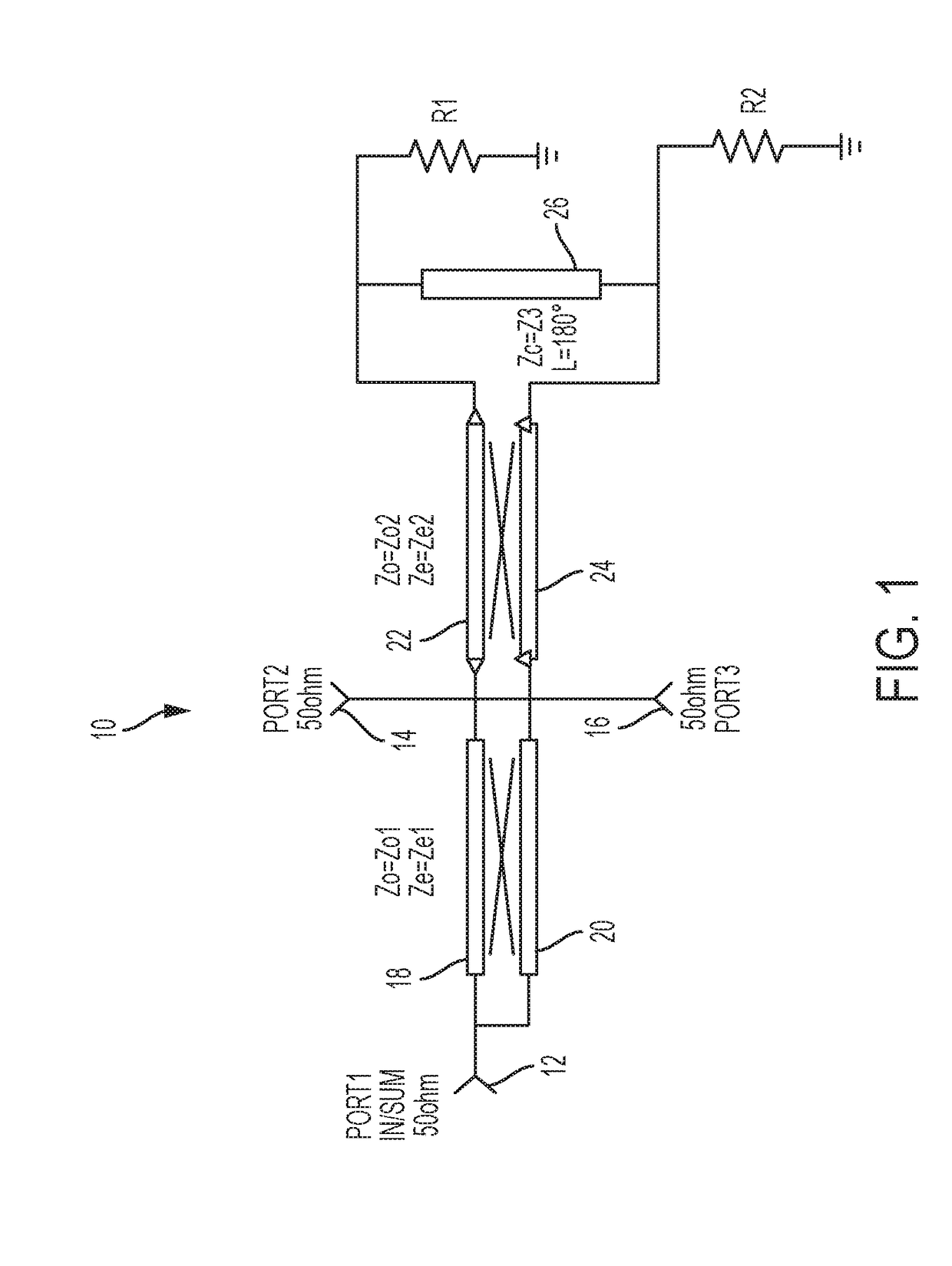
[0020]Referring to the figures, wherein like numerals refer to like parts throughout, there is seen in FIG. 1 a schematic of a power divider 10 according to the present invention. Power divider 10 comprises a first port 12 coupled to a second port 14 and a third port 16 via a first set of coupled transmission lines 18 and 20. Second port 14 and third port 16 are further connected to a pair of directly grounded isolation resistors R1 and R2 via a second set of coupled transmission lines 22 and 24. A long transmission line 26 extends between second set of coupled transmission lines 22 and 24. First port 12 is shown as functioning an input port, while second port 14 and third port 16 function as output ports for power dividing. It should be recognized that power divider 10 could be used as a combiner by using second port 14 and third port 16 as inputs, and first port 12 as an output.

[0021]Coupled transmission lines 18 and 20 have the parameters Ze1, Zo1, θ1 and coupled transmission lin...


PUM


Abstract

A power divider capable of implementation in a compact multilayer surface mount component to perform power division/combining with low insertion loss, wide bandwidth, design flexibility and high power handling capabilities. The power divider has a first pair of coupled transmission lines interconnecting the input to the outputs, a second pair of coupled transmission lines interconnecting the output ports to grounded isolation resistors, and a single transmission line interconnecting the second pair of coupled transmission lines. The surface mount implementation is by a first layer supporting the ports, a second layer providing edge coupled lines, a third layer having ground plane, a fourth layer and a fifth layer each supporting one of a pair of broadside coupled lines, a sixth layer with another ground plane, and a seventh layer including a single line interconnecting the broadside coupled lines.

Description

BACKGROUND OF THE INVENTION1. Field of the Invention[0001]The present invention relates to power dividers / combiners and, more specifically, to a surface mount power divider / combiner for wide bandwidth and high power applications.2. Description of the Related Art[0002]Power dividers and combiners are fundamentals passive devices in microwave engineering. Wireless systems greatly rely on power splitting / combining tasks to achieve target performance for many different applications, such as high power amplifiers, phased arrays antennas, oscillators, mixers and modulators. Wilkinson and the Gysel power dividers are popular choices for power division with equal phase at the output ports, with the Gysel architecture being more useful in high power applications.[0003]A Wilkinson power divider uses quarter-wave transformers to match the output ports to the common port. An isolation resistor of value 2 Zo is added between the output ports, which imposes limitations for frequency operation, po...

Claims


Application Information

Patent Timeline
IPC IPC(8): H01P5/10H03H7/48H01P5/16H01P5/04H05K1/02
CPCH01P5/1007H03H7/48H05K1/0237H01P5/04H01P5/16H01P5/187
Inventor SENIOR, DAVIDMEI, CHONG
Owner TTM TECH INC
Why Eureka
Try Eureka