
Low-temperature distillation plant

a distillation plant and low temperature technology, applied in the field of low-temperature distillation facilities, can solve the problems of non-condensable gases, slow process, condensation of vapour, etc., and achieve the effects of improving the ltd facility, increasing the energy requirement, and slowing down the distillation process

Active Publication Date: 2019-02-21
THERMAL PURIFICATION TECH LTD
View PDF5 Cites 0 Cited by
  • Summary
  • Abstract
  • Description
  • Claims
  • Application Information

AI Technical Summary

Benefits of technology

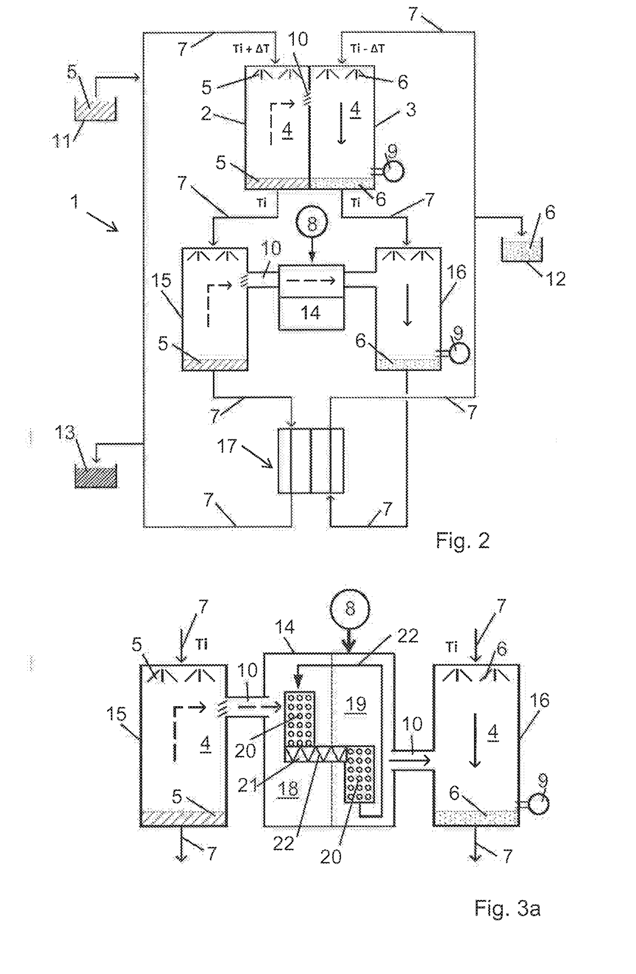
The present invention aims to improve a LTD facility by reducing its energy requirements for maintaining fluid temperatures. This is achieved by using a heat exchanger with a counter-flow device to release waste heat from hot fluid onto cold mixed fluid, which is then needed for the LTD process. The technical effect is an efficient use of energy in the LTD process.

Problems solved by technology

The somewhat cooler, injected pure fluid inevitably causes the condensation of the vapour arising from the somewhat warmer mixed fluid due to evaporation.
What is important is that non-condensable gases are sucked out of the condenser at the end of the condensation path, since they unfavourably influence the pressure in the vapour space and slow down the process.
Such industrial facilities, for example power stations, are often constructed on rivers or at other expanses of waters, whose temperatures noticeably increase due to the cooling of the industrial facility, which is often undesirable.
In particular, waste heat of less than 100° C. cannot often be meaningfully which is to say economically utilised and thus burdens the environment.
However, facilities for distilling fluid are also required at locations, at which no waste heat is available.
In these cases, the costs for the energy required for reaching the respectively demanded temperature of the fluids are thus part of the operating costs.
The disadvantage of this arrangement is the fact that such a facility operates in a very energy-intensive manner.
These have the disadvantageous effect that they are at odds with the optimal process conditions, by which means the process is slowed down in all chambers.
The disadvantage with this is evidently the fact that the already clean vapour is mixed again with the impure fluid and condenses at least partly by way of this.
This increases the energy requirement and slows down the distillation process.

Method used


Image

  • Low-temperature distillation plant
  • Low-temperature distillation plant
  • Low-temperature distillation plant

Examples


Embodiment Construction

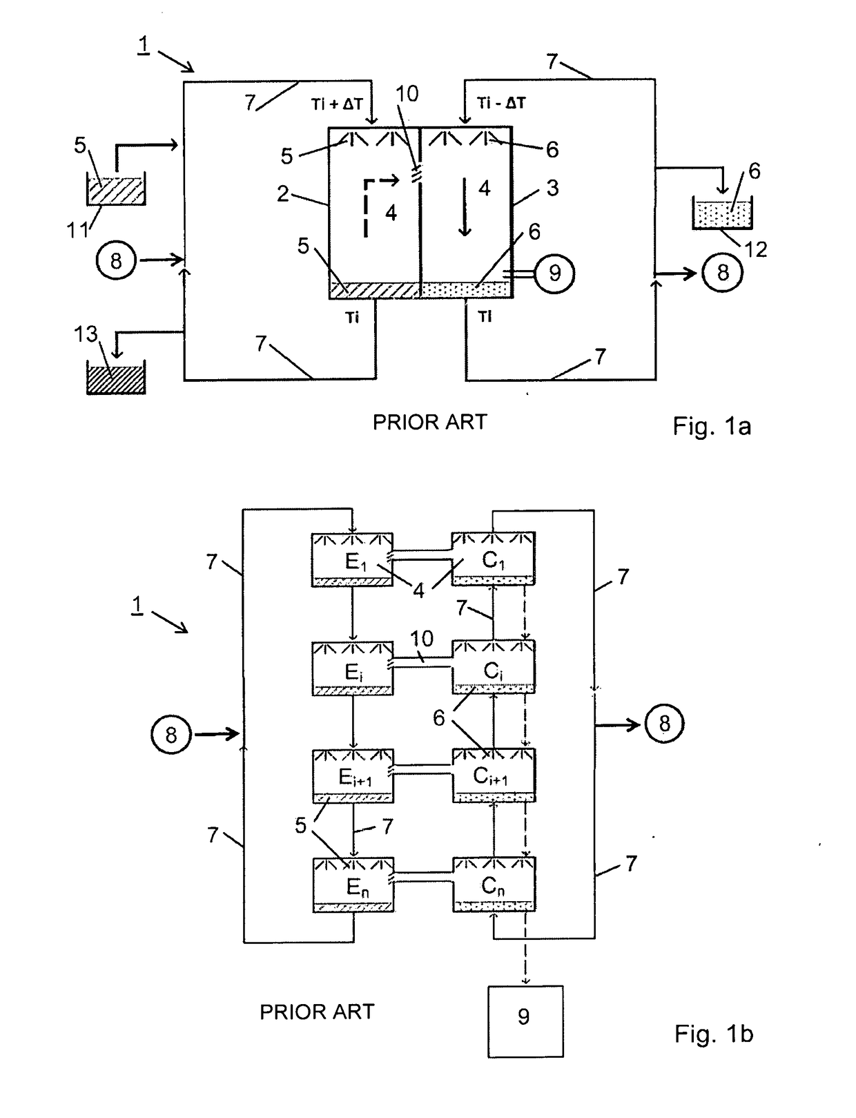
[0024]FIG. 1a shows a schematic representation of a low-temperature distillation facility (LTD facility) 1 according to the state of the art, in its simplest embodiment with only one stage. It comprises an evaporator 2 with a vapour space 4, into which mixed fluid 5 which is to be distilled can be introduced, so as to evaporate. Non-evaporated mixed fluid 5 is also captured again in the evaporator 2. The LTD facility moreover comprises a condenser 3 with a vapour space 4, into which pure fluid 6 corresponding to the distillate of the mixed fluid 5 can be sprayed, in order to form the smallest of droplets, on which vapour can condense. These droplets are finally captured again in the condenser 3, as a pure fluid 6. The vapour spaces 4 of the evaporator 2 and the condenser 3 in each case are connected to one another into a common vapour space 4 by way of a vapour connection 10, in a manner such that the pressure and the temperature can propagate therein at all times in an unhindered m...


PUM

PropertyMeasurementUnit
temperatures Tiaaaaaaaaaa
pressureaaaaaaaaaa
temperatureaaaaaaaaaa

Abstract

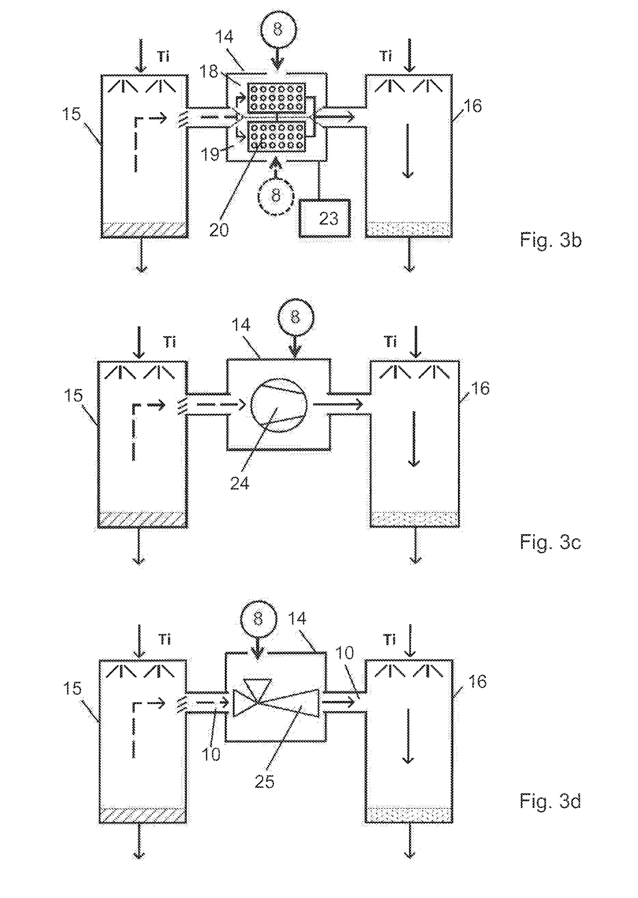
A low-temperature distillation facility for distilling a mixed fluid into a pure fluid. An aggregation device has an inlet connected to the vapour space of a supercooling chamber, wherein captured mixed fluid from an evaporator enters the supercooling chamber. The aggregation device's outlet is connected to the vapour space of a superheating chamber, wherein captured pure fluid from a condenser can be sprayed into the superheating chamber. An energy source cools the temperature in the supercooling chamber and heats the temperature in the superheating chamber. A heat exchanger is arranged between the exits of the supercooling chamber and of the superheating chamber. During the process, vapour flows from the supercooling chamber via the aggregation device to the superheating chamber.

Description

CROSS-REFERENCE TO RELATED APPLICATIONS[0001]This application claims priority to International Application Serial No. PCT / EP2017 / 050346, filed Jan. 9, 2017, which claims priority to Swiss Application No. 0004 / 16, filed Jan. 12, 2016. International Application Serial No. PCT / EP2017 / 050346 is hereby incorporated herein in its entirety for all purposes by this reference.FIELD OF THE INVENTION[0002]The invention relates to a low-temperature distillation facility (LTD) with one or more stages having different mean temperatures Ti, for distilling a mixed fluid into a pure fluid, wherein each stage comprises an evaporator with a vapour space and with a warmer Ti+ΔT mixed fluid which can be brought in, as well as a condenser with a vapour space and with a cooler Ti−ΔT pure fluid which can be sprayed in. The vapour spaces of the evaporator and of the condenser are connected to one another into a common vapour space by way of vapour connections, in a manner such that the pressure and the temp...

Claims


Application Information

Patent Timeline
Patent Type & Authority Applications(United States)
IPC IPC(8): B01D5/00B01D1/26B01D1/16B01D3/00B01D1/28C02F1/04C02F1/12
CPCB01D5/006B01D1/26B01D1/16B01D3/007B01D5/0027B01D5/0036B01D5/0039B01D1/289C02F1/041C02F1/12C02F2303/10Y02A20/124B01D3/065
Inventor LEHMANN, MARKUS
Owner THERMAL PURIFICATION TECH LTD
Learn More