
Protective layers for micro-fluid ejection devices and methods for depositing same

a technology of protective layers and micro-fluid ejection, which is applied in the direction of ohmic-resistance heating, ohmic-resistance heating details, printing, etc., can solve the problems of mechanical shock to the thin metal layer comprising the ink ejection device, less heat conductive cavitation and protective layers, and increase the overall ejection head temperature. , to prolong the life of the micro-fluid ejection device, the effect o

Inactive Publication Date: 2010-12-23
LEXMARK INT INC
View PDF1 Cites 3 Cited by
  • Summary
  • Abstract
  • Description
  • Claims
  • Application Information

AI Technical Summary

Benefits of technology

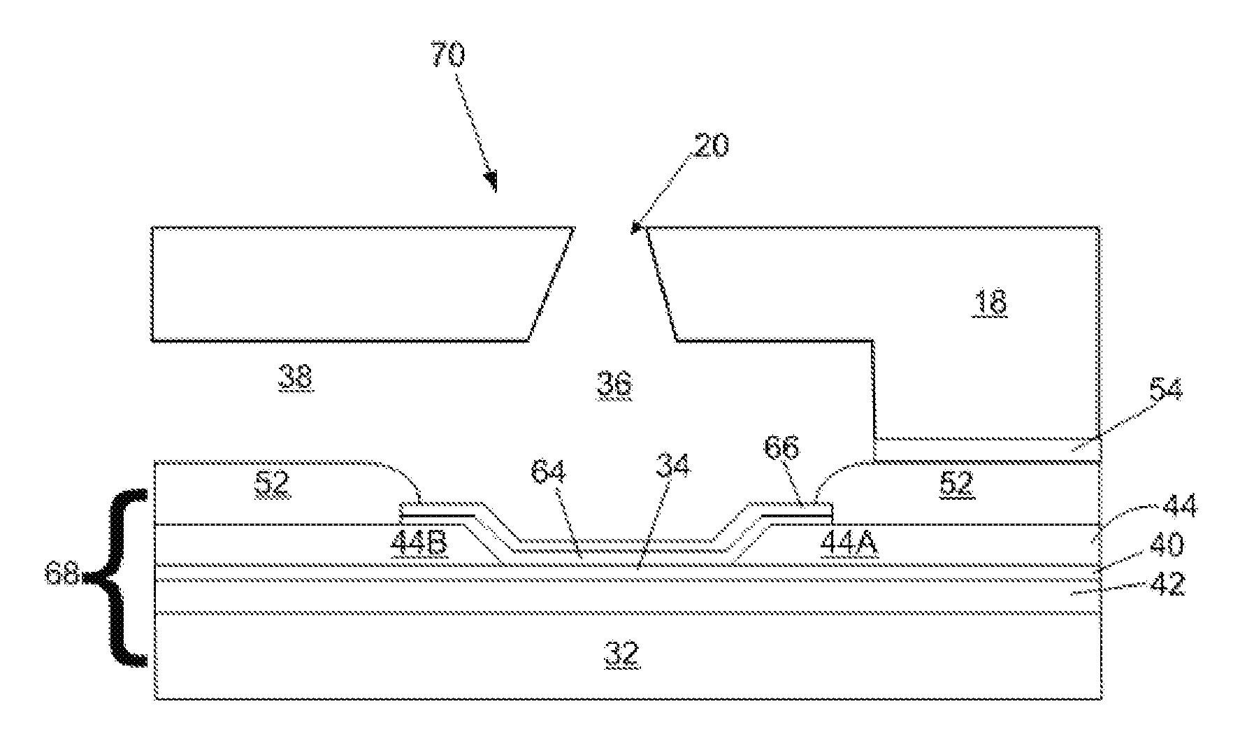
The patent text describes a micro-fluid ejection device with improved protective layers for the heater resistors used in the device. The invention aims to reduce energy consumption, increase speed of operation, and lower manufacturing costs. The patent describes a heater chip with a resistive layer and a cavitation layer, as well as a method for making the heater chip. The technical effects of the invention include reduced energy requirements, improved adhesion between the protective layer and the cavitation layer, and reduced number of layers in the heater chip. The invention is particularly suitable for ink jet printers, where the micro-fluid ejection device is a part of the ink jet printer cartridge.

Problems solved by technology

After the ink is ejected, the bubble collapses causing mechanical shock to the thin metal layers comprising the ink ejection device.
One disadvantage of the multilayer thin film heater construction is that the cavitation and protective layers are less heat conductive than the underlying resistive layer.
Increased energy input to the heater resistors not only increases the overall ejection head temperature, but also reduces the frequency of drop ejection thereby decreasing the speed of operation of the ejection device.

Method used


Image

  • Protective layers for micro-fluid ejection devices and methods for depositing same
  • Protective layers for micro-fluid ejection devices and methods for depositing same
  • Protective layers for micro-fluid ejection devices and methods for depositing same

Examples


Embodiment Construction

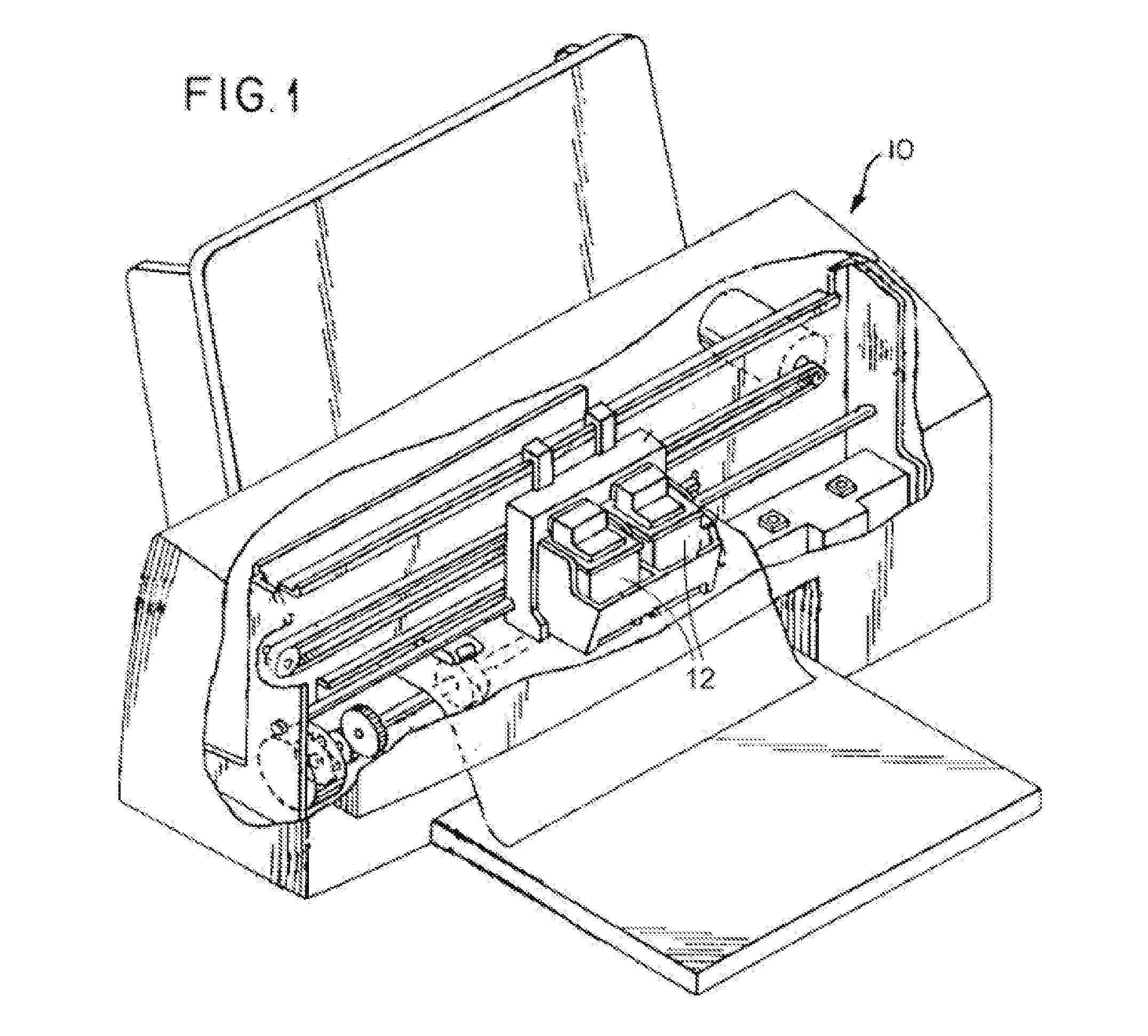
[0017]Embodiments as described herein are particularly suitable for micro-fluid ejection devices, for example, the micro-fluid ejection devices described herein may be used in ink jet printers. An ink jet printer 10 is illustrated in FIG. 1 and includes one or more ink jet printer cartridges 12 containing the micro-fluid ejection devices described in more detail below.

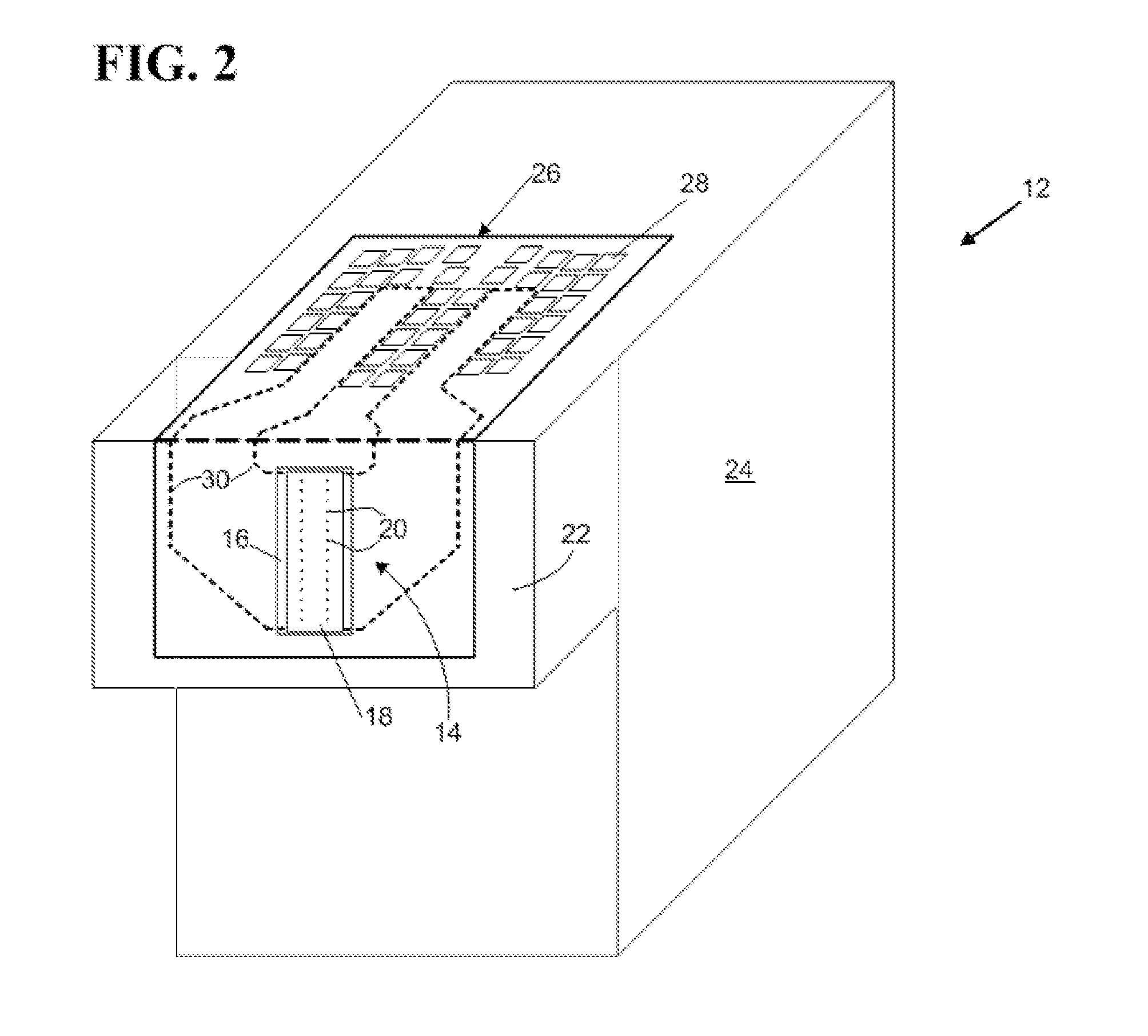
[0018]An exemplary ink jet printer cartridge 12 is illustrated in FIG. 2. The cartridge 12 includes a printhead 14, also referred to herein as an example of “a micro-fluid ejection head.” The micro-fluid ejection head 14 includes a substrate 16 and an attached nozzle plate 18 having nozzles 20. The ejection head 14 is attached to an ejection head portion 22 of the cartridge 12. A main body 24 of the cartridge 12 includes a fluid reservoir for supplying a fluid such as ink to the ejection head 14. A flexible circuit, such as tape automated bonding (TAB) circuit 26, containing electrical contacts 28 for connection to the...


PUM


Abstract

Heater chips for a micro-fluid ejection device, such as those having a reduced energy requirement and more efficient production process therefor. One such heater chip includes a resistive layer deposited adjacent to a substrate and a protective layer deposited adjacent to the resistive layer. The protective layer can be a tantalum oxide protective layer, which has a high breakdown voltage. An optional cavitation layer of tantalum, which bonds well with the tantalum oxide layer, may be deposited adjacent to the protective layer. Alternatively, for example, the tantalum oxide layer may serve as both the protective layer and the cavitation layer.

Description

[0001]This application claims priority and benefit as a continuation application of U.S. patent Ser. No. 11 / 427,549, filed Jun. 29, 2006.TECHNICAL FIELD[0002]The disclosure relates to micro-fluid ejection devices and, in particular, in one exemplary embodiment, to improved protective layers and methods for making the improved protective layers for heater resistors used in micro-fluid ejection devices.BACKGROUND AND SUMMARY[0003]In the production of thermal micro-fluid ejection devices such as ink jet printheads, a cavitation layer is typically provided as an ink contact layer for a heater resistor. The cavitation layer prevents damage to the underlying dielectric (protective) and resistive layers during ink ejection. Between the cavitation layer and heater resistor there are typically one or more layers of a passivation material to reduce ink corrosion of the heater resistor. As ink is heated in an ink chamber by the heater resistor, a bubble forms and forces ink out of the ink cham...

Claims


Application Information

Patent Timeline
Patent Type & Authority Applications(United States)
IPC IPC(8): B41J2/05H05B3/02
CPCB41J2/14129B41J2202/03B41J2/1646B41J2/1603
Inventor CORNELL, ROBERT WILSONGUAN, YIMINJOYNER, II, BURTON LEE
Owner LEXMARK INT INC
Learn More