Automatic current switching of current leads for superconducting magnets

a superconducting magnet and current lead technology, applied in the field of magnetic resonance imaging, can solve the problems of increasing the energy requirements of operating the superconducting magnet, and the difficulty of connecting and disconnecting the current leads from the coils of the superconducting magn

Inactive Publication Date: 2015-02-12
KONINKLIJKE PHILIPS ELECTRONICS NV
View PDF0 Cites 4 Cited by
  • Summary
  • Abstract
  • Description
  • Claims
  • Application Information

AI Technical Summary

Benefits of technology

[0047]In another embodiment the first and second rigid current loops are located in a region where a significant axially directed magnetic field appears if the magnet is on. The combined effect of this magnetic field on the current through the loops is to generate a lateral electromagnetic force. This lateral electromagnetic force may be used for actuating the first switch and/or the second s...

Problems solved by technology

A difficulty in connecting current leads to a superconducting magnet is that good conductors of electricity are typically good thermal conductors.
This may increase th...

Method used


Image

  • Automatic current switching of current leads for superconducting magnets
  • Automatic current switching of current leads for superconducting magnets
  • Automatic current switching of current leads for superconducting magnets

Examples


Embodiment Construction

[0062]Like numbered elements in these figures are either equivalent elements or perform the same function. Elements which have been discussed previously will not necessarily be discussed in later figures if the function is equivalent.

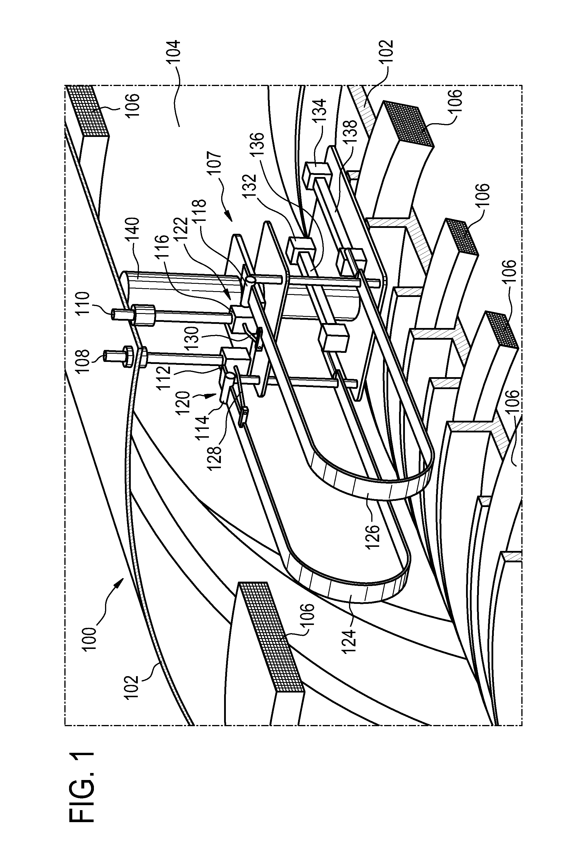
[0063]FIG. 1 illustrates an example of a magnet 100 according to an embodiment of the invention. This is a portion of a cylindrical-type magnet. There are visible vacuum chamber walls 102. This magnet has a cylindrical-type bore in the middle. Between the walls 102 there is a vacuum chamber 104. The elements labeled 106 are portions of superconducting coils which form the magnet circuit 106.

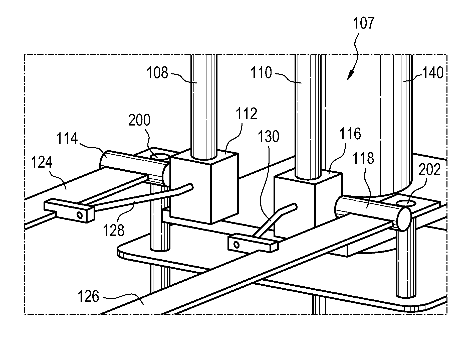
[0064]There is a switch assembly 107 mounted within the vacuum chamber 104. There is a first current lead 108 and a second current lead 110 which go through the wall 102 and provide an electrical feed-through. The first current lead 108 is connected to a first contact 112. The second current lead 110 is connected to a third contact 116. There is a second contact 114 ...


PUM


Abstract

The invention provides for magnetic resonance imaging system (600) comprising a superconducting magnet (100) with a first current lead (108) and a second current lead (110) for connecting to a current ramping system (624). The magnet further comprises a vacuum vessel (104) penetrated by the first current lead and the second current lead. The magnet further comprises a magnet circuit (106) within the vacuum vessel. The magnet circuit has a first magnet circuit connection (132) and a second magnet circuit connection (134). The magnet further comprises a first switch (120) between the first magnet connection and the first current lead and a second switch (122) between the second magnet connection and the second current lead. The magnet further comprises a first current shunt (128) connected across the first switch and a second current shunt (130) connected across the second switch. The magnet further comprises a first rigid coil loop (124) operable to actuate the first switch. The first rigid coil loop forms a portion of the first electrical connection. The magnet further comprises a second rigid coil loop (126) operable to actuate the second switch. The second rigid coil loop forms a portion of the second electrical connection.

Description

TECHNICAL FIELD[0001]The invention relates to magnetic resonance imaging, in particular it relates to the automatic switching of current leads for ramping the current of a superconducting magnet.BACKGROUND OF THE INVENTION[0002]A magnetic field is used in Magnetic Resonance (MR) Imaging to align the nuclear spins of atoms as part of the procedure for producing images within the body of a patient. This magnetic field is referred to as the B0 field. During an MR scan, Radio Frequency (RF) pulses generated by a transmitter or amplifier and an antenna cause perturbations to the local magnetic field and can be used to manipulate the orientation of the nuclear spins relative to the B0 field. Radio Frequency (RF) signals emitted by the nuclear spins are detected by a receiver coil, and these RF signals are used to construct the MRI images.[0003]The B0 field for magnetic resonance imaging is typically generated using a superconducting magnet. The current flowing in the coils of the supercon...

Claims


Application Information

Patent Timeline
IPC IPC(8): G01R33/36G01R33/34H01F6/06G01R33/3815
CPCG01R33/3642H01F6/06G01R33/34G01R33/3815H01F6/008H01F6/065H01H36/008
Inventor OVERWEG, JOHANNES ADRIANUSAMTHOR, THOMAS ERIKFORTHMANN, PETERUHLEMANN, FALKDAVID, BERND
Owner KONINKLIJKE PHILIPS ELECTRONICS NV
Why Eureka
Try Eureka