Glass panel unit and glass window
a glass window and glass panel technology, applied in the direction of parallel plane units, synthesized resin layered products, chemistry apparatus and processes, etc., can solve the problems of not being beneficial and easy to ensure a sufficient thickness, and achieve the effect of less easily recognizable to the viewer and good stability
- Summary
- Abstract
- Description
- Claims
- Application Information
AI Technical Summary
Benefits of technology
Problems solved by technology
Method used
Image
Examples
first embodiment
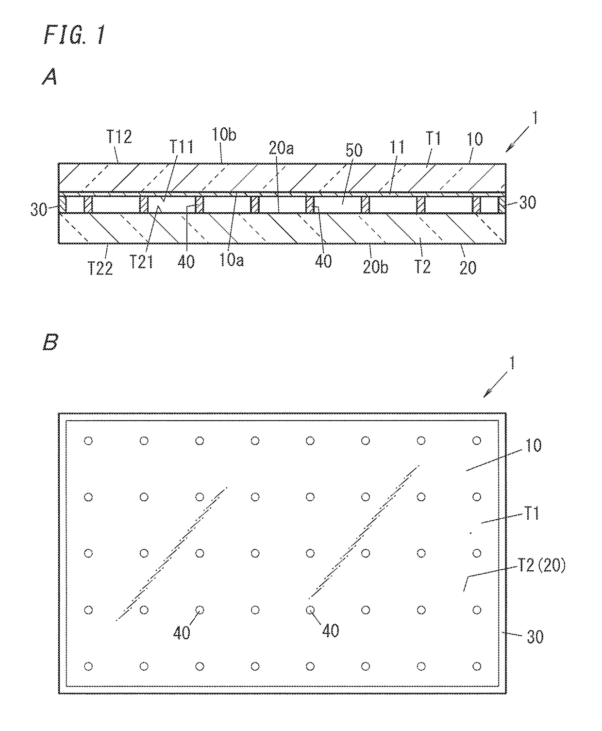
[0023]FIGS. 1A and 1B illustrate an exemplary glass panel unit (hereinafter referred to as a “glass panel unit 1”). The glass panel unit 1 is schematically illustrated in FIGS. 1A and 1B. Particularly in a glass panel unit 1 such as the one illustrated in FIG. 1A, the dimensions of respective portions thereof are not necessarily to scale and may be different from actual ones. For example, the thickness of the glass panel unit 1 is illustrated to be larger than the actual one to facilitate the reader's understanding. In addition, the spacers 40 are also illustrated in a larger size than actual ones. In this drawing, FIG. 1A illustrates a cross-sectional view of an exemplary glass panel unit 1, while FIG. 1B illustrates a plan view of the exemplary glass panel unit 1.
[0024]The glass panel unit 1 is basically transparent, and therefore, members inside of the glass panel unit 1 (such as the frame member 30 and the spacers 40) may be visible through the glass panel unit 1. FIG. 1B illust...
second embodiment
[0136]FIGS. 8A and 8B illustrate an exemplary glass panel unit 1 according to this embodiment. Specifically, FIG. 8A illustrates a cross-sectional view of the exemplary glass panel unit 1 according to this embodiment, and FIG. 8B is a plan view illustrating the details of the exemplary glass panel unit 1 according to this embodiment. In the following description, any constituent member of the second embodiment having the same function as its counterpart of the first embodiment will be designated by the same reference numeral as that counterpart's, and a detailed description thereof will be omitted herein.
[0137]The glass panel unit 1 according to this embodiment includes the first panel T1 including at least the first glass plate 10, the second panel T2 including at least the second glass plate 20, the frame member 30, the spacers 40, and the vacuum space 50 as described above. The glass panel unit 1 further includes a third panel T6, a sealer member 71, and a dry gas space 81. The t...
third embodiment
[0150]FIG. 9 illustrates a plan view of an exemplary glass window 9 according to this embodiment. More specifically, FIG. 9 is an exemplary plan view of the glass window 9 in a situation where the spacers 40 are recognizable to the viewer.
[0151]The glass window 9 includes the glass panel unit 1 according to either the first embodiment or the second embodiment. The glass window 9 further includes a window frame 91 fitted to an outer peripheral portion of the glass panel unit 1 extending along the edges thereof.
[0152]The window frame 91 has an exposed surface 91 which is exposed externally. Thus, this glass window 9 may be fitted to some fixtures, for example, with the exposed surface 91 facing outside. Examples of the fixtures include wall openings, front doors, and indoor doors. If the glass window 9 is fitted to some fixture, then the second surface of one panel selected from the group consisting of the first panel T1, the second panel T2, and the third panel T6 may be exposed outs...
PUM
| Property | Measurement | Unit |
|---|---|---|
| Nanoscale particle size | aaaaa | aaaaa |
| Structure | aaaaa | aaaaa |
| Absorption edge | aaaaa | aaaaa |
Abstract
Description
Claims
Application Information
 - R&D
- Intellectual Property
- Life Sciences
- Materials
- Tech Scout
- Unparalleled Data Quality
- Higher Quality Content
- 60% Fewer Hallucinations
Browse by: Latest US Patents, China's latest patents, Technical Efficacy Thesaurus, Application Domain, Technology Topic, Popular Technical Reports.
© 2025 PatSnap. All rights reserved.Legal|Privacy policy|Modern Slavery Act Transparency Statement|Sitemap|About US| Contact US: help@patsnap.com


