Lighting device having a wireless communication antenna

a wireless communication and wireless communication technology, applied in semiconductor devices, lighting and heating apparatus, light source combinations, etc., can solve the problem that the introduction of wireless communication typically requires considerably more space for electronic components, and achieve the effect of preventing or minimizing the amount of direct current electrical power and efficiently receiving control signals

Active Publication Date: 2019-02-21
SIGNIFY HLDG BV
View PDF0 Cites 3 Cited by
  • Summary
  • Abstract
  • Description
  • Claims
  • Application Information

AI Technical Summary

Benefits of technology

[0012]The present invention is based on the realization that at least one power line of a lighting device may be utilized as a wireless communication antenna, and that wireless signals may be received, or transmitted, by superimposing the wireless signal on top a direct current carried by power lines in a lighting device. Thereby, the at least one power line provides an additional function and the cost of a lighting device having wireless communication may be reduced. The antenna does not take up any space on a substrate, e.g. the carrier and the use of substrate material may be reduced. The introduction of wireless communication typically requires considerably more space for electronic components, especially the antenna. The present invention provides a solution using components already present, which means that no additional space is required. The reduced need for a substrate, or substrate space, achieved by forming the antenna with at least one power line, may therefore reduce the problem of degassing volatile organic compounds, VOCs, and moisture release within the envelope. A reduced amount of degassing of VOCs inside the envelope means that less oxygen is needed to prevent a degradation of the solid state light sources. A reduced amount of moisture release within the envelope means less risk of degradation of the solid state light sources. Further, the antenna formed by the at least one power line is not shielded, e.g. surrounded, by metal parts and may have good reception. The reception property of the antenna may be tuned by configuring the antenna length.
[0016]In at least one exemplary embodiment, the lighting device further comprises a first radio frequency choke connected in series between the antenna portion and the driver circuitry, and a second radio frequency choke connected in series between the antenna portion and the solid state light sources. The first and second radio frequency chokes may efficiently delimit which portion of the at least one power line is utilized as an antenna portion. Further, the radio frequency chokes prevents, or at least minimizes, alternating electrical power reaching the solid state light sources and the driver circuitry.
[0017]In at least one exemplary embodiment, the lighting device further comprises a direct current choke connected in series between the at least one power line and the wireless communication circuit. The direct current choke prevents, or at least minimizes, the amount of direct current electrical power which reaches the more delicate circuitry of the wireless communication circuitry from the at least one power line. It should be noted that the wireless communication circuitry may still be driven by the driver circuitry, e.g., by an additional feeder wire and not the connection to the at least one power line.
[0018]In at least one exemplary embodiment, a length of the at least one power line is configured to correspond to a specific frequency at which the lighting device is to receive control signals. Thereby, the at least one power line may more efficiently receive control signals. The power line may be provided in pre-determined length, at assembly, or the length of the power lines may be configured through cutting the at least one power line.
[0019]In at least one exemplary embodiment, the lighting device further comprises an exhaust tube arranged inside the envelope, the carrier may be a tubular light source carrier attached to the exhaust tube, the exhaust tube being arranged partly inside the tubular light source carrier. By “exhaust tube” is meant a tube through which a gas may be introduced into the lighting device during production and which is later sealed. Exhaust tubes are often found in general lighting service (GLS) bulbs, i.e. conventional incandescent light bulbs. During the production of such light bulbs, the exhaust tube allows for air to be exhausted from the bulb and an inert gas to be pumped into the bulb. Modern lighting devices based on SSL technology may also have an exhaust tube for introducing a gas into the envelope that encloses the solid state light sources. The gas may improve the heat transfer from the solid state light sources as well as the lifetime of the lighting device by reducing lumen depreciation of the solid state light sources. The exhaust tube is electrically isolating and may for example be made of glass. A tubular light source carrier promotes efficient heat transfer from the light sources by creating convection currents through the carrier. In other words, the tubular light source carrier may give rise to a thermal chimney effect where a fluid circulates through the tubular light source carrier.
[0020]In at least one exemplary embodiment, the wireless communication circuit is arranged on the carrier. In other words, the wireless communication circuit may be positioned completely inside the envelope, supported by the light source carrier. Thereby, the wireless communication circuit does not need a separate carrier. Further, this may facilitate electrically connecting the wireless communication circuit to the solid state light sources for example via the carrier. Alternatively, the wireless communication circuit may be arranged outside the envelope. This means that fewer electronic components need to be placed within the atmosphere within the envelope which may reduce the amount degassing of VOCs and the amount of moisture in the envelope.

Problems solved by technology

The introduction of wireless communication typically requires considerably more space for electronic components, especially the antenna.

Method used


Image

  • Lighting device having a wireless communication antenna
  • Lighting device having a wireless communication antenna
  • Lighting device having a wireless communication antenna

Examples


Embodiment Construction

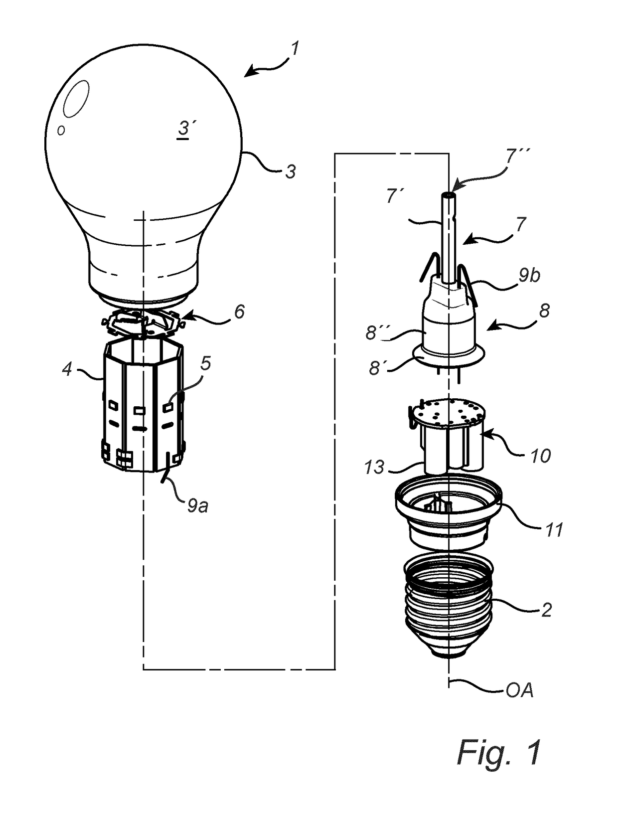
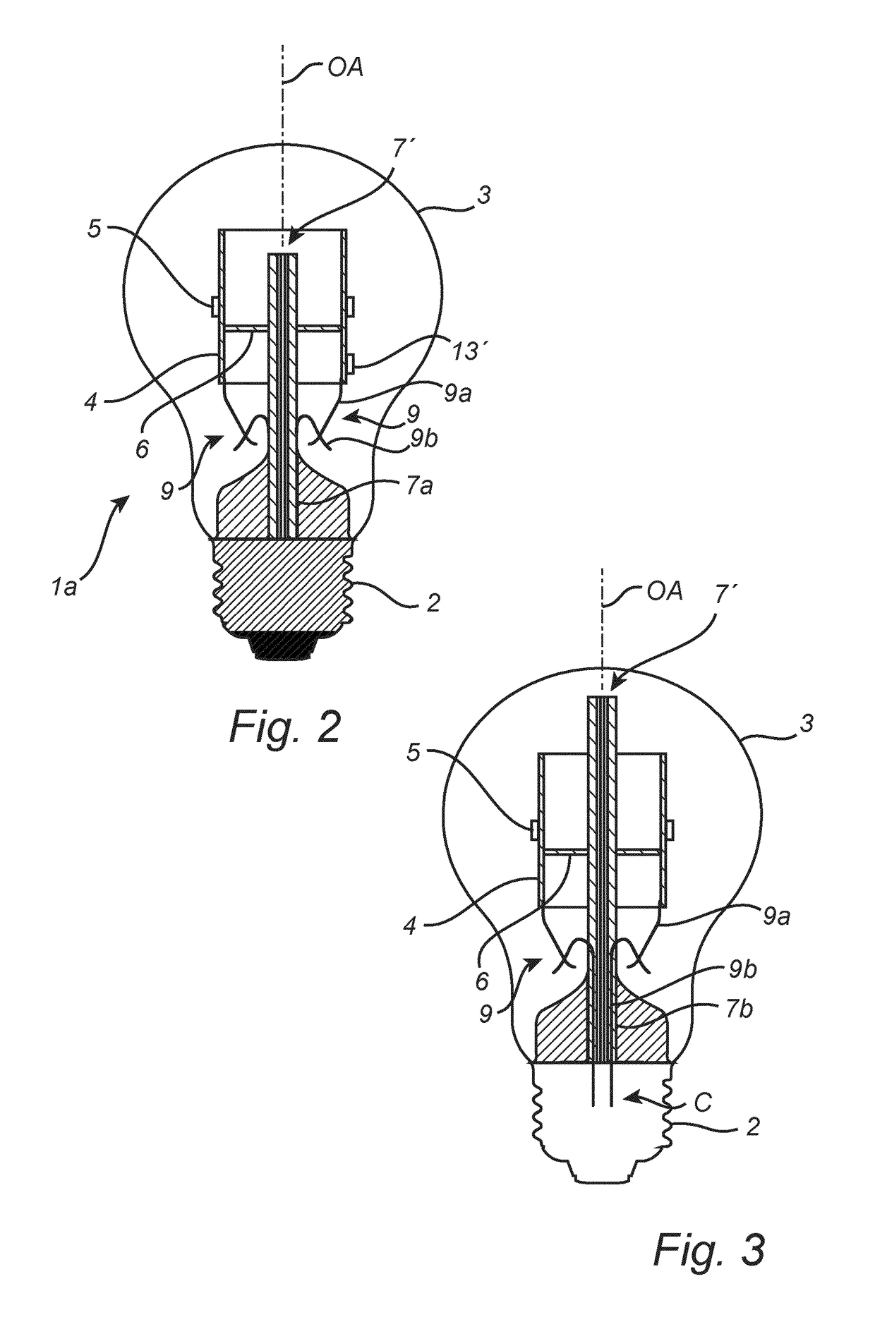
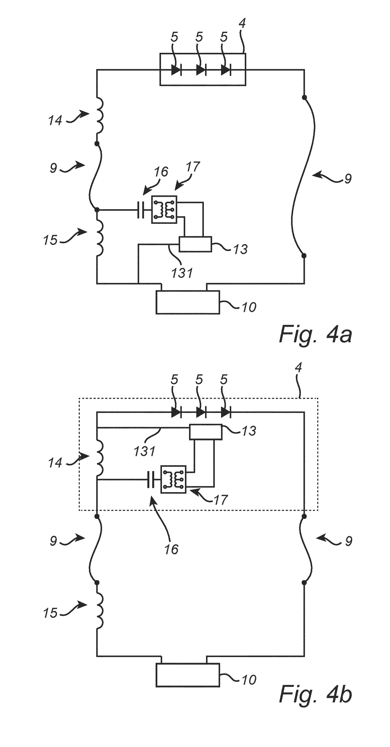
[0030]In the present detailed description, exemplary embodiments of a lighting device according to the present invention are mainly discussed with reference to schematic views showing a lighting device according to various embodiments of the invention. It should be noted that this by no means limits the scope of the invention, which is also applicable in other circumstances for instance with other types or variants of lighting device or components than the embodiments shown in the appended drawings. Further, that specific components are mentioned in connection to an embodiment of the invention does not mean that those components cannot be used to an advantage together with other embodiments of the invention. The invention will now be described with reference to the enclosed drawings where first attention will be drawn to the structure, and secondly to the function. Like reference characters refer to like elements throughout the description.

[0031]The present invention will now be des...


PUM

PropertyMeasurementUnit
radio frequenciesaaaaaaaaaa

Abstract

The present invention relates to a lighting device (1, 1a) comprising an envelope (3), a carrier (4) arranged inside the envelope (3) and having solid state light sources (5) mounted on the carrier (4), driver circuitry (10) spaced apart from the carrier (4), at least one power line (9) connecting the solid state light sources (5) and the driver circuitry (10), and a wireless communication circuit (13) for receiving control signals, and for controlling the light output, during operation, from the solid state light sources (5). The wireless communication circuit (13) is connected to the at least one power line (9) for using the at least one power line (9) as a wireless communication antenna.

Description

FIELD OF THE INVENTION[0001]The present invention relates to a lighting device having a wireless communication antenna.BACKGROUND OF THE INVENTION[0002]Lighting devices based on solid state lighting (SSL) technology which have an antenna for wireless control of the solid state light sources are known in the art. The intensity and color of the emitted light may for example be controlled in this way. A lighting device of this type is disclosed in WO 2013014821 A1. That lighting device has an antenna that may be arranged inside or around a support member for a semiconductor light emitting element.[0003]It is desirable to find ways to incorporate antennas into the designs of existing lighting devices without significant modifications so that the addition of unnecessary costs and complexity to the production process is avoided.[0004]GB 2468612 discloses a vehicle mounted patch antenna apparatus. The apparatus has a ground conductor which is arranged on a substrate. An antenna element is ...

Claims


Application Information

Patent Timeline
Patent Type & Authority Applications(United States)
IPC IPC(8): F21K9/238H01Q1/46F21K9/237F21V23/00F21V23/04F21V31/04F21K9/232H05B37/02H05B44/00
CPCF21K9/238H01Q1/46F21K9/237F21V23/002F21V23/0435F21V31/04F21K9/232H05B37/0272F21V23/003F21K9/64F21Y2115/10F21Y2103/00F21V29/503F21Y2115/15F21Y2115/30F21Y2113/13H01Q1/44F21Y2107/30F21V3/10H05B47/19
Inventor GIELEN, VINCENT STEFAN DAVIDLOUH, YACOUBA
Owner SIGNIFY HLDG BV
Why Eureka
Try Eureka