Memeasuring a cavity by means of interference spectroscopy

a technology of interference spectroscopy and cavity, which is applied in the direction of interferometers, using reradiation, instruments, etc., can solve the problems of requiring a large investment in resources to calibrate wavelength, weak dependence of signal on movement of objects, and inability to distinguish in this manner between changes in the length of the cavity and changes in other optical parameters. , to achieve the effect of increasing the accuracy of analysis

Active Publication Date: 2019-02-21
HABRICH BJORN
View PDF3 Cites 2 Cited by
  • Summary
  • Abstract
  • Description
  • Claims
  • Application Information

AI Technical Summary

Benefits of technology

[0020]This frequency calibration can take place in particular through a numerical fit to the frequency fR of the absorption line of the absorption material. Alternatively or in addition, it can be advantageous to calibrate the frequency f of the coherent light source by using a reference interferometer 60 of known length.
[0021]The frequency f of the coherent light source is tuned cyclically. In each cycle, the frequency of the laser is tuned uniformly from a start- to a target-value (

Problems solved by technology

It is problematic here that it requires great investment in resources to calibrate the wavelength and keep it constant.
In addition a problem arises in the vicinity of the extreme points of the sinus, since there the dependence of the signal on the movement of the object is weaker.
Furthermore one cannot distinguish in this manner between changes in the length of the cavity and changes in other optical parameters such as, for example, the reflectivity and/or the index of refraction.
Several lasers, however, mean at the same time greatly increased investment in resources and thus increased costs.Through high-frequency modulation of the wavelength of the tuneable lasers at a small amplitude, which in effect corresponds to a small movement of the target, in addition to the interference signal its approximated first derivative by

Method used


Image

  • Memeasuring a cavity by means of interference spectroscopy
  • Memeasuring a cavity by means of interference spectroscopy
  • Memeasuring a cavity by means of interference spectroscopy

Examples


Embodiment Construction

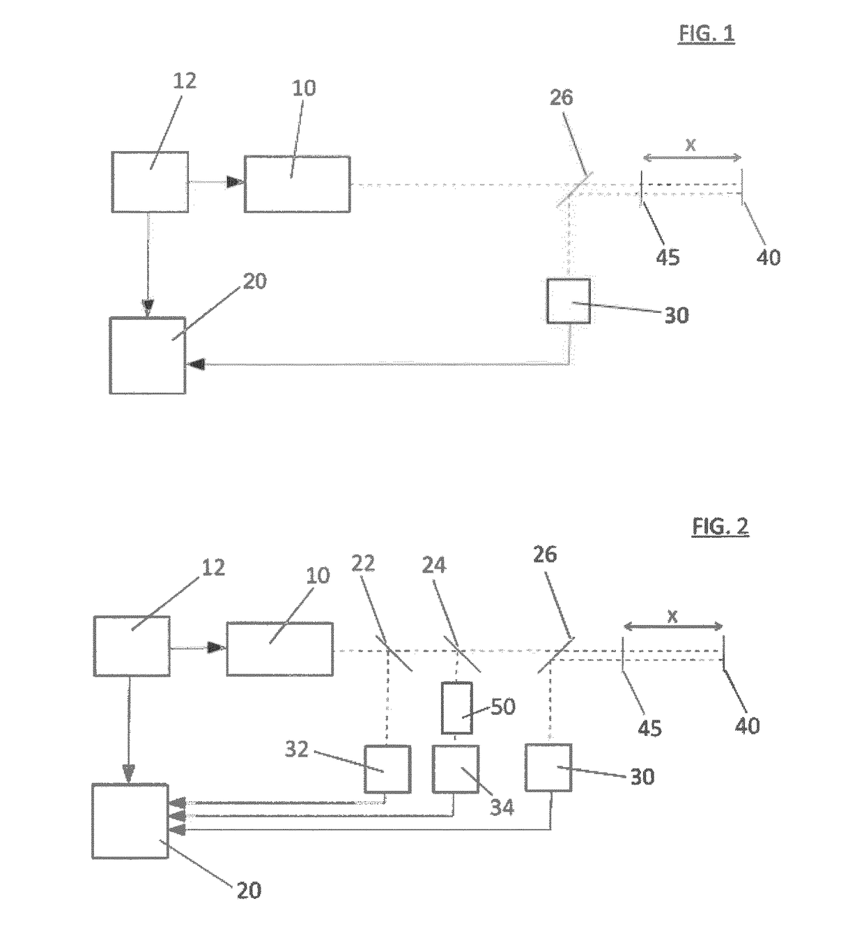
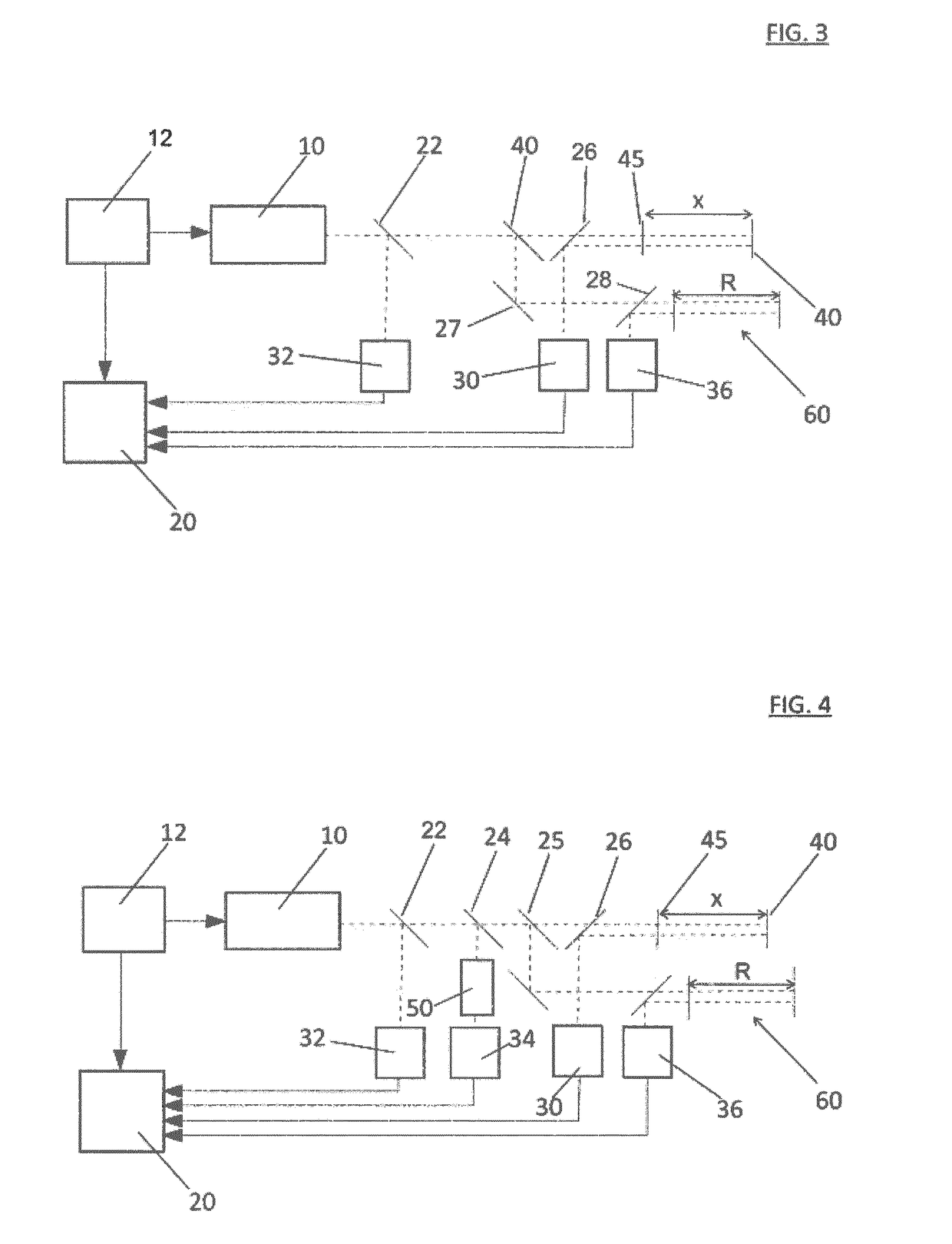
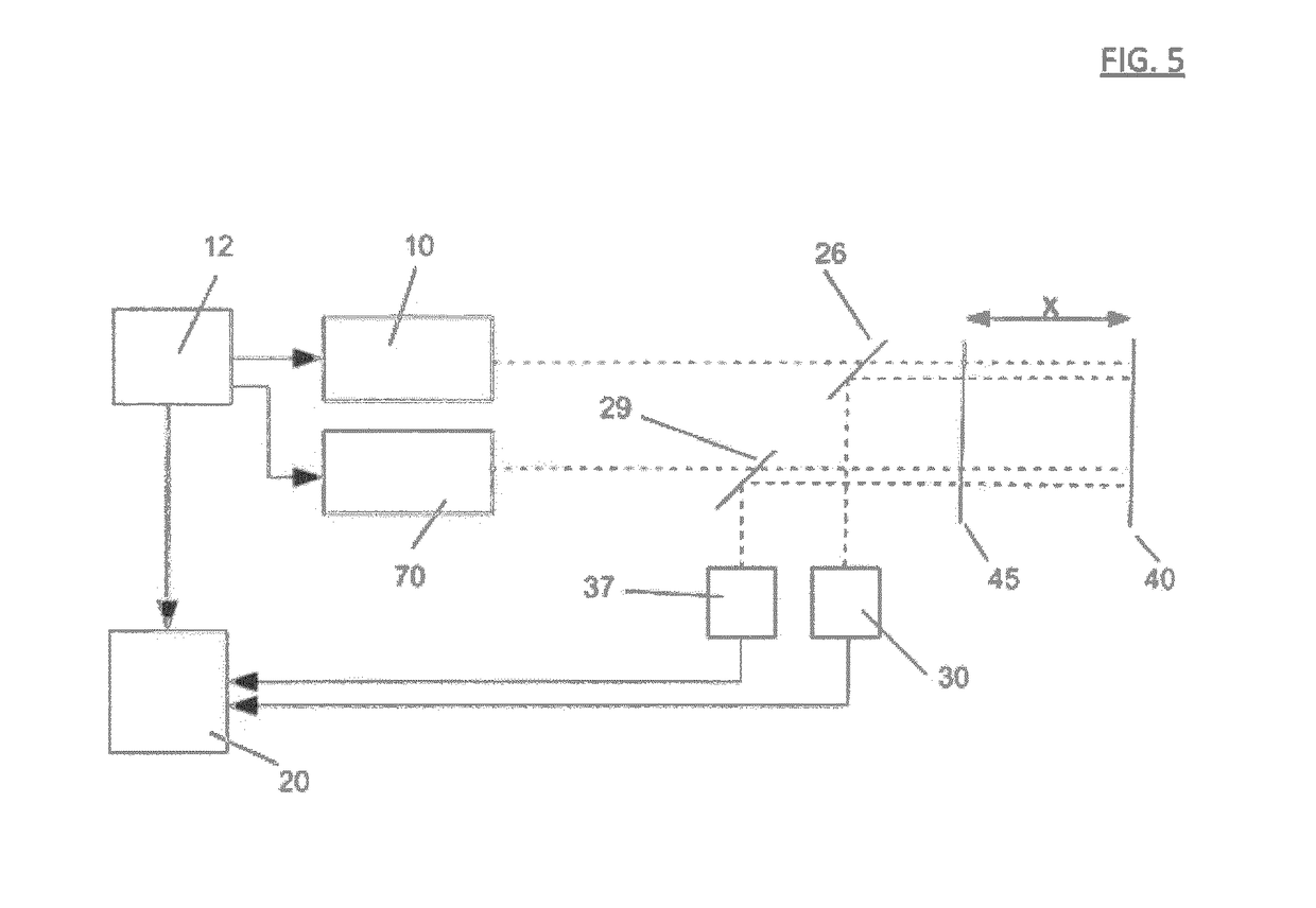
[0036]FIG. 1 shows a schematic representation of a first embodiment example of a device according to the invention for the interferometric determination of the mechanical / geometric and the optical properties of a cavity. Here, as in the following illustrations, the basic principle of the construction of the device is shown. Appliances for calibration, power supply, temperature control etc are not shown, nor are optical ancillary appliances such as apertures, collimators etc. For better understanding, moreover, the emitted and incident beams are shown in the drawings next to each other. In fact, however, usually these beams are not separated geometrically.

[0037]A tuneable laser, e.g. a DFB laser diode, which preferably radiates visible or infrared light, serves in the shown embodiment examples as a coherent light source 10 for beam generation. A modulation unit 12 is envisaged for frequency tuning. The tuning here can take place e.g. thermally by means of temperature control, electri...


PUM


Abstract

A method for interferometrically determining geometric and/or optical parameters of a cavity comprises the method steps of: tuning the frequency f of a coherent light source (10) over a frequency range Δf, deriving a target beam and a reference beam from the coherent light source (10), wherein the target beam passes through the cavity at least once, generating an interference signal I(f) which is dependent on the frequency f of the light source by superimposing the reference beam on the target beam, capturing an interference spectrum of the interference signal I(f) over the frequency range Δf of the frequency f of the coherent light source, evaluating a plurality of measurement points of the captured interference spectrum over the frequency range Δf by numerically fitting the measurement points to a mathematical function produced, and determining the geometric and/or optical parameters of the cavity (40, 45) by determining the parameters of the mathematical function produced.

Description

FIELD OF THE INVENTION[0001]The invention concerns a method and a device for interferometric measurement of the various optical and mechanical parameters of a cavity, in particular its length.BACKGROUND TO THE INVENTION[0002]Every interferometer relies on the principle of superimposing an internal reference beam on a coherent light beam reflected from the target and analysing the resulting interference signal.[0003]The interference signal changes in different ways, depending on which parameters of the cavity change. In the case of length changes of the interferometer (of the cavity) or due to wavelength changes of the coherent light source, there is a sweep-through of the phase of the periodic (sine- or cosine-shaped) interference signal. The speed of this phase change is proportional to the speed of a length change of the cavity or the speed of a wavelength change of the light source multiplied by the current length of the cavity. In the case of changes to other optical parameters ...

Claims


Application Information

Patent Timeline
IPC IPC(8): G01B9/02G01B11/02G01B11/14G01N21/41G01N21/45G01S17/32G01S17/34
CPCG01B9/02004G01B11/02G01B11/14G01B9/0207G01B9/02083G01N21/4133G01N21/45G01S17/325G01B2290/60G01B9/02057G01S17/34G01S7/497
Inventor HABRICH, BJORN
Owner HABRICH BJORN
Why Eureka
Try Eureka