Device, method and program for optimization analysis

a technology of optimization analysis and optimization method, applied in the field of optimization analysis, can solve the problems of inability to obtain the clue for obtaining the optimal solution in a short period of time, the analysis system cannot calculate the cost of design drawings, and the product development man-hour and design man-hour increase, so as to improve the analysis efficiency and analysis accuracy

Inactive Publication Date: 2006-03-09
FUJITSU LTD
View PDF6 Cites 24 Cited by
  • Summary
  • Abstract
  • Description
  • Claims
  • Application Information

AI Technical Summary

Benefits of technology

[0010] The present invention relates to optimization analysis for achieving target values and it is an object thereof to enhance the analysis efficiency and analysis accuracy.

Problems solved by technology

Also, a conventional analysis system can not calculate costs from design drawings and, furthermore, a dedicated cost calculation system must be launched for a cost calculation.
Therefore, product development man-hours and design man-hours increase.
Also, in the aspect of costs, since the cost calculation can not be performed from materials, dimensions and process method reflected on the drawings, a clue for obtaining an optimum solution can not be found in short period of time.

Method used


Image

  • Device, method and program for optimization analysis
  • Device, method and program for optimization analysis
  • Device, method and program for optimization analysis

Examples


first embodiment

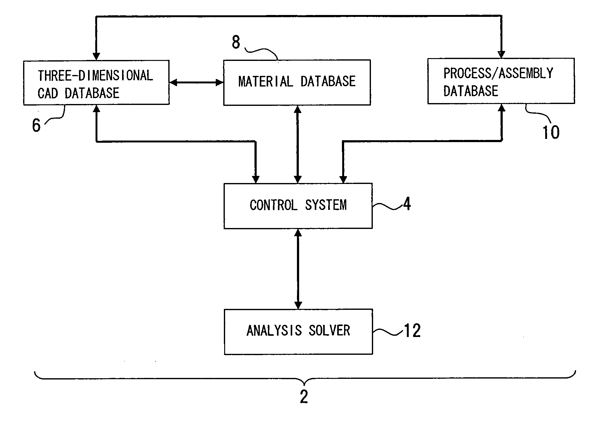
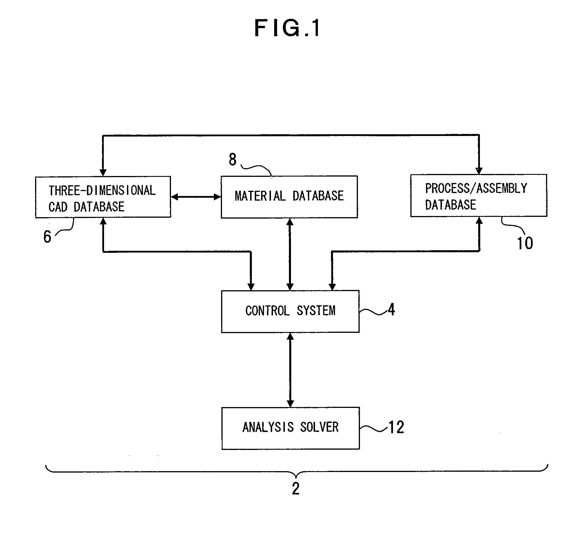
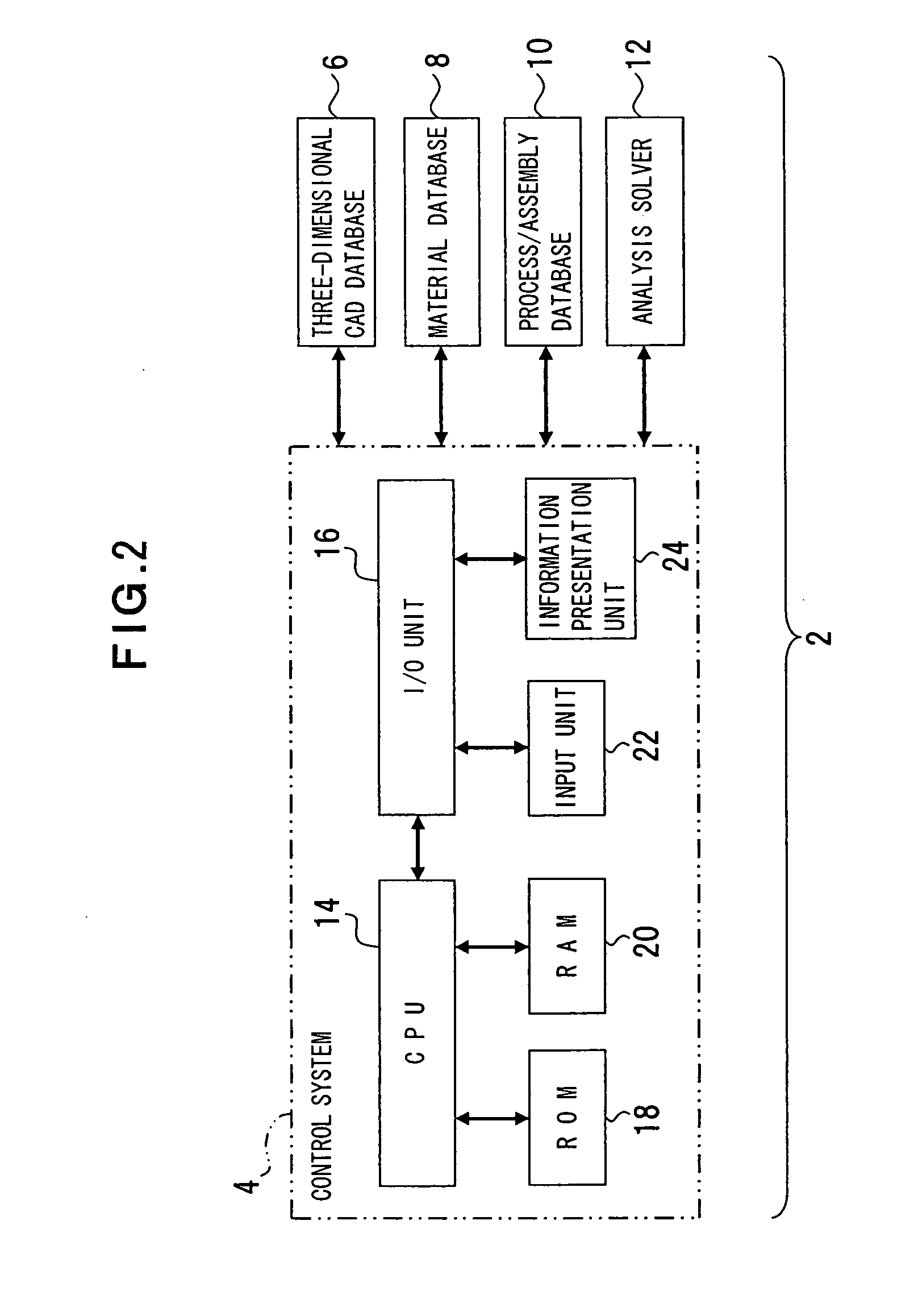
[0040] A first embodiment of the present invention will be described with reference to FIGS. 1 and 2. FIG. 1 shows an optimization analysis device in accordance with a first embodiment and FIG. 2 shows a hardware structure of a control system in the optimization analysis device.

[0041] The optimization analysis device 2 closely coordinates a plurality of systems for setting analysis conditions, enhances simplicity and continuity (seamlessness) of access to the systems and, specifically, establishes a data format intervening between a control sequence and an analysis input file or a result file. The optimization analysis device 2 in accordance with this embodiment is shown as an application example of a substrate design, is comprised of a control system 4 executing an optimization analysis as core and coordinates the control system 4, a three-dimensional CAD (Computer Aided Design) database 6, a material database 8, a process / assembly database 10 and an analysis solver 12. The contro...

second embodiment

[0051] A second embodiment of the present invention will be described with reference to FIGS. 4, 5 and 6. FIG. 4 shows an optimization analysis device in accordance with the second embodiment; FIG. 5 shows a flowchart showing processing procedures of the analysis solver; and FIG. 6 shows an example of a data map of a material database. The same symbols are imparted to the same portion as the first embodiment.

[0052] The control system 4 is comprised of various functions such as an analysis condition selection function and priority selection function 26, a result determination function 28, a search function 30, an analysis data generation function 32, an analysis solver change function 34 and a price conversion function 36. The analysis condition selection function and priority selection function 26 is a function for selecting the analysis conditions, adding priorities to the analysis conditions and selecting the analysis conditions in order of the priority. The result judgment funct...


PUM


Abstract

The present invention relates to optimization analysis achieving a target value and provides a device, method and program ensuring improved analysis efficiency and analysis accuracy. The device includes an analysis unit (CPU 14), an evaluation unit (CPU 14) and a condition modification unit (CPU 14). The analysis unit executes an analysis with analysis conditions imparted thereto. The evaluation unit evaluates the analysis results. The condition modification unit modifies the analysis conditions imparted to the analysis unit, based on the evaluation results. An optimum solution is thus derived by performing one or more analyses through the modification of the given analysis conditions.

Description

BACKGROUND OF THE INVENTION [0001] 1. Field of the Invention [0002] The present invention relates generally to optimization analysis for use in structural analysis for e.g., designing products and evaluating their reliabilities, and, more particularly, to a device, method and program for optimization analysis which attempt to streamline the analysis by enabling access to a plurality of systems for e.g., setting and modifying analysis conditions. [0003] 2. Description of the Related Art [0004] For the structural analysis, although a concept referred to as an “inverse analysis” conventionally exists, the inverse analysis remains confined to finding values as a simulation. Although a solver with an “optimum calculation” function conventionally exists, the optimum calculation remains to the degree of a function for cutting down dimensions (models) and increasing the thickness. Also, a conventional analysis system can not calculate costs from design drawings and, furthermore, a dedicated...

Claims


Application Information

Patent Timeline
Patent Type & Authority Applications(United States)
IPC IPC(8): G21C17/00G06F11/30G06F15/00
CPCG06F17/50G06Q40/08G06F2217/80G06F2217/16G06F2119/08G06F2111/10G06F30/00
Inventor NAKADATE, MAMIITOH, NOBUTAKA
Owner FUJITSU LTD
Why Eureka
Try Eureka